 |
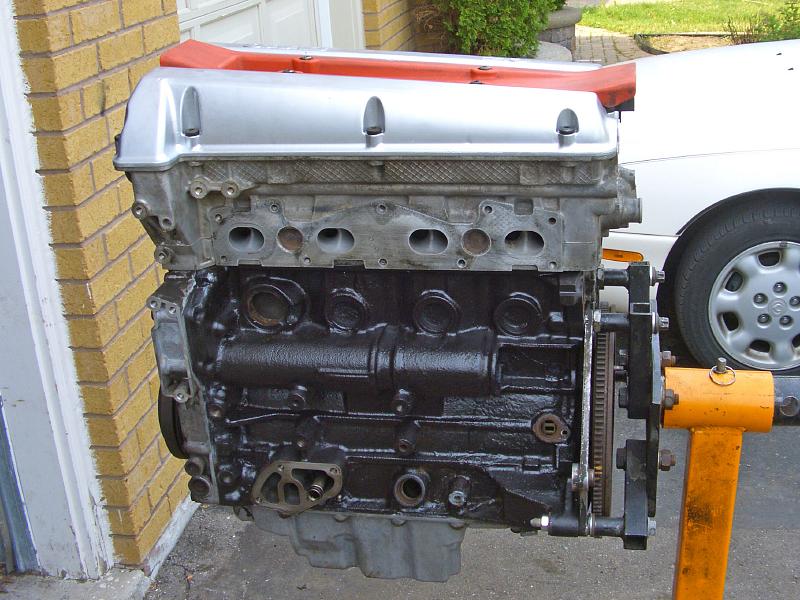
| 09.07.2006: Engine |
|
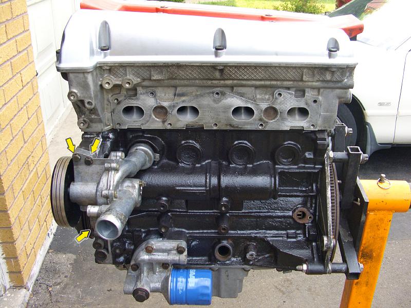
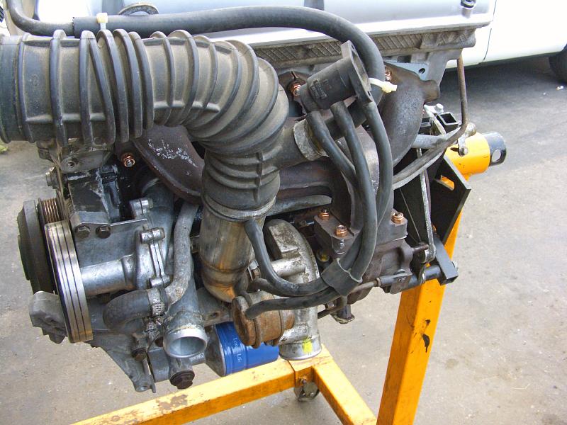
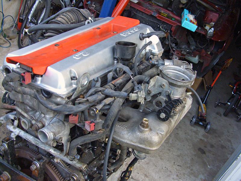
A freshly rebuilt engine just waiting to go back into the car.
|
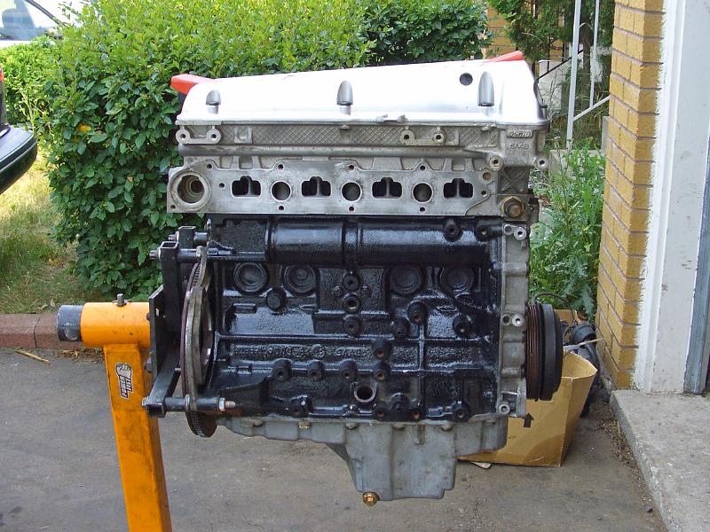 |
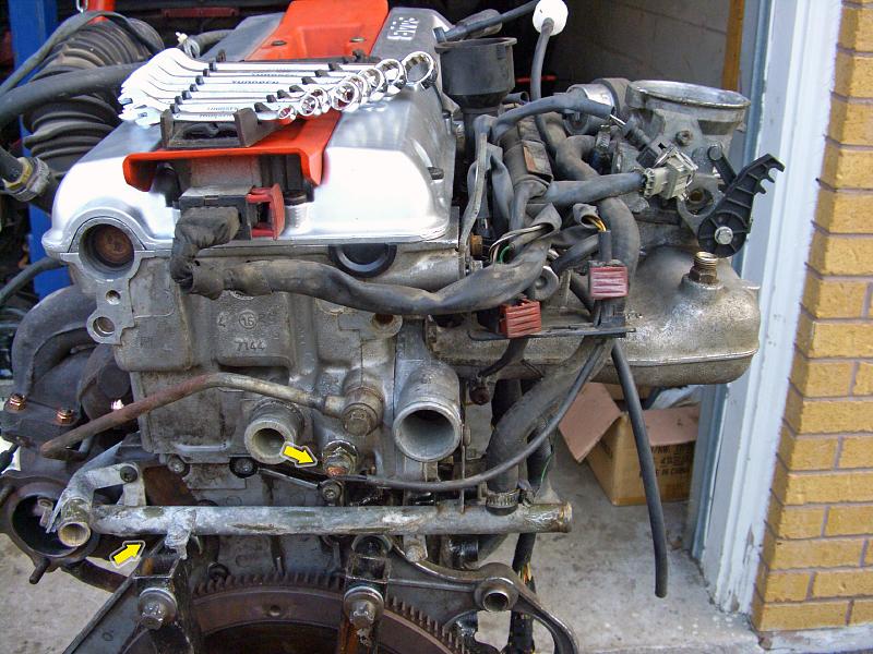
| 09.07.2006: Engine |
|
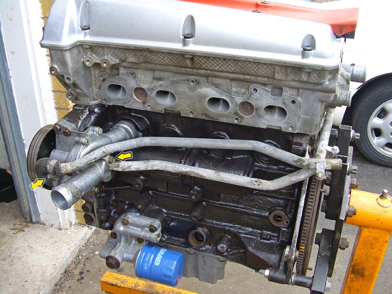
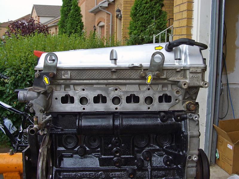
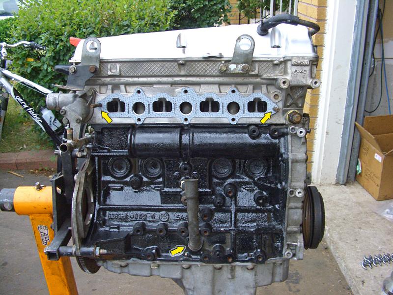
Refer to
this document for
more detail on the base engine assembly.
|
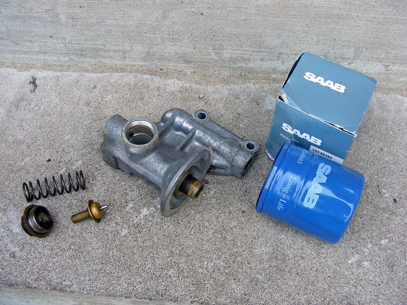 |
| 09.07.2006: Oil filter housing |
|
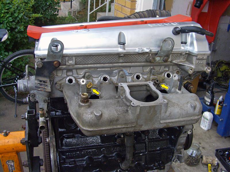
Clean the oil filter housing, the oil thermostat, and get a new filter ready.
|
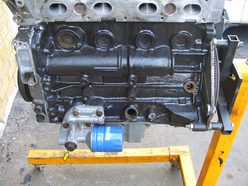 |
| 09.07.2006: Oil filter |
|
Install the filter housing (13 mm socket), tighten the thermostat cap
(22 mm). Lubricate the O-ring on the filter and screw it on.
|
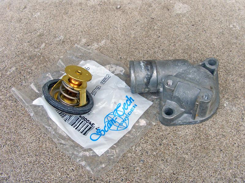 |
| 09.07.2006: Thermostat |
|
Fit a new seal on the thermostat and clean the thermostat housing.
|
 |
| 09.07.2006: Thermostat housing |
|
Attach the thermostat housing (12 mm socket).
|
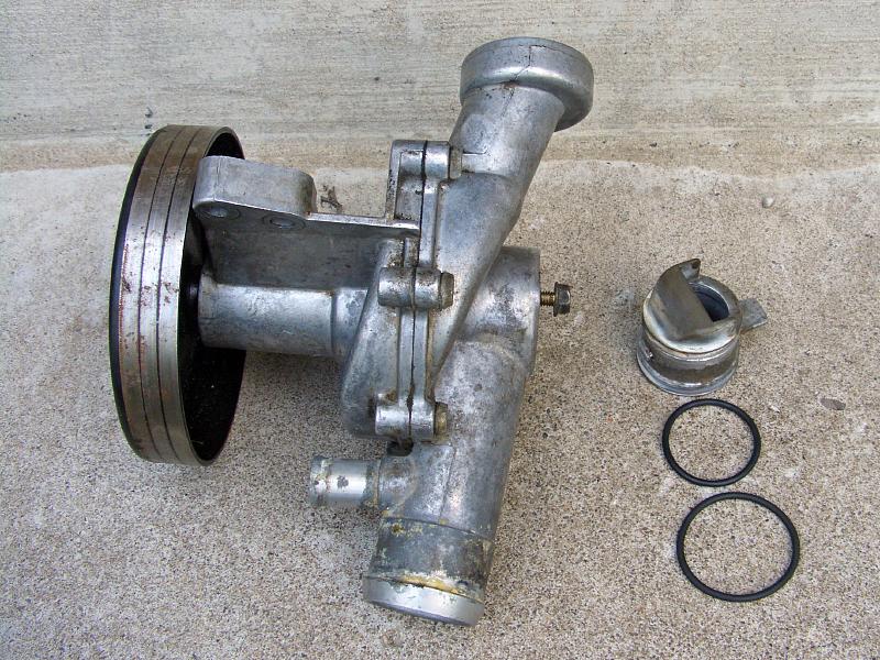 |
| 09.07.2006: Coolant pump |
|
The coolant pump is next. Coat new O-rings with vaseline and put them
on the coolant inlet pipe.
|
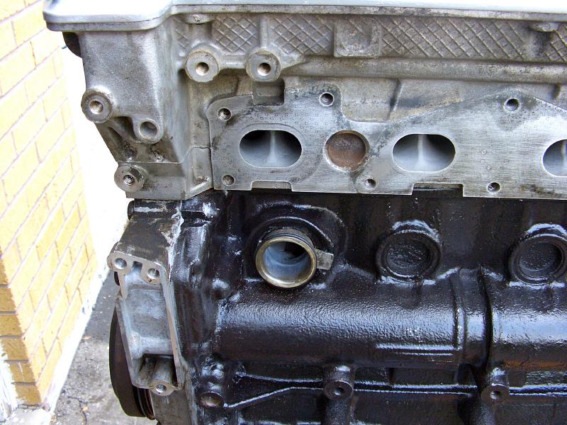 |
| 09.07.2006: Coolant inlet |
|
Fit the inlet into the slot in front of cylinder #1. Make sure the flap
on the inlet matches the cut-out on the right.
|
 |
| 09.07.2006: Pump installed |
|
Install the coolant pump, check that the outer O-ring on the inlet is not
jammed. Tighten the bolts.
|
 |
| 09.07.2006: Coolant pipes |
|
Attach the pipes leading to the heat exchanger and expansion tank. Renew
the O-ring and the short rubber U-bend if needed. Tighten the 10 mm screw
on the pump.
|
 |
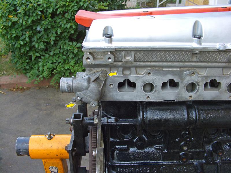
| 09.07.2006: Coolant pipes |
|
Secure the pipes on the far side of the engine -- one screw at the
corner, and two more on the thermostat housing.
|
 |
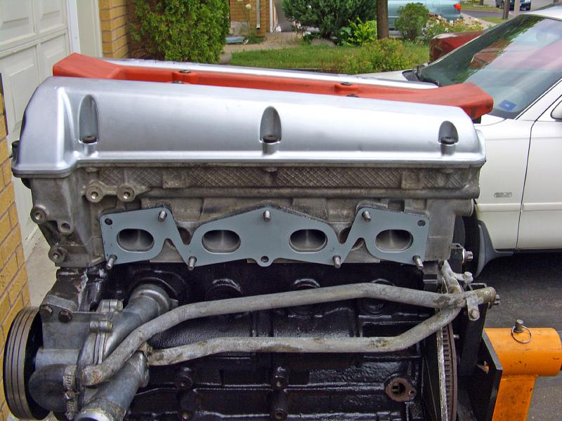
| 09.07.2006: Manifold studs |
|
Screw in exhaust manifold studs. The factory configuration has longer studs
in the outer holes, but the benefit of those is debatable since they are
always the first to break, so I'm using short studs instead.
|
 |
| 09.07.2006: Exhaust gasket |
|
Position a new gasket on the studs -- soft side to the head,
flat side to the manifold.
|
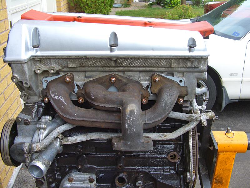 |
| 09.07.2006: Exhaust manifold |
|
Install the manifold, fit the washers and tighten the nuts to 18.5 ft-lbs
(13 mm socket).
|
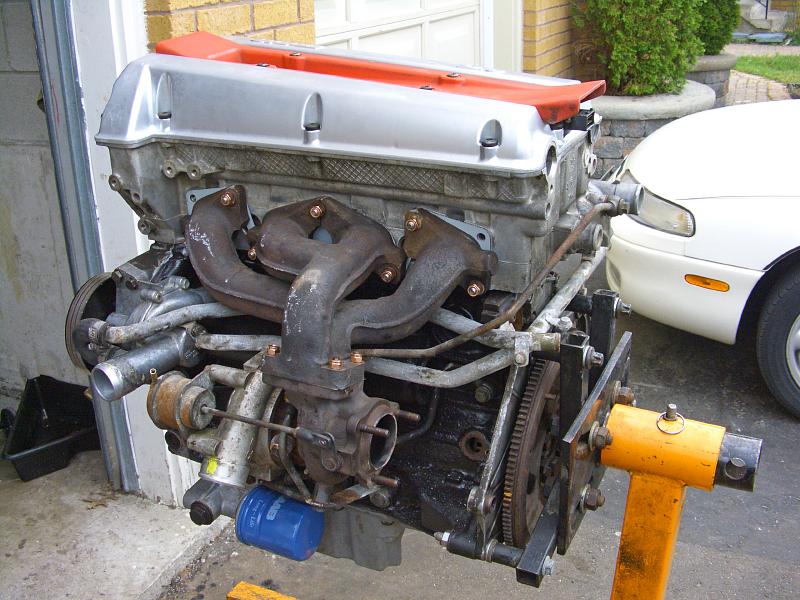 |
| 09.07.2006: Turbocharger |
|
Bolt the turbocharger to the exhaust manifold, use a fresh gasket.
Install the lower support bar. Connect all coolant and
oil lines before tightening the banjo bolts. Renew all banjo bolt washers.
More detail on turbo fitting in this article.
|
 |
| 09.07.2006: Mount bracket |
|
Install the passenger side engine mount bracket (two 16 mm bolts).
|
 |
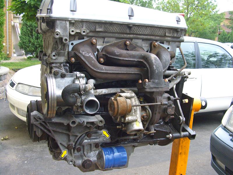
| 09.07.2006: Inlet pipe |
|
Bolt the inlet pipe to the turbocharger and fit three hoses from
the boost pressure control valve (BPC). Attach the crankcase vent pipe.
|
 |
| 09.07.2006: Lifting eyes |
|
Connect the crankcase vent nipple to the valve cover. Install the lifting
eyes and the wiring harness bracket above the thermostat housing.
|
 |
| 09.07.2006: Intake gasket |
|
Fit the lower part of the oil dipstick tube.
Insert two studs into the intake manifold mounting holes (you'll be replacing
them with regular bolts later) and position the gasket on them.
|
 |
| 09.07.2006: Intake manifold |
|
Install the intake manifold and tighten the bolts to 16 ft-lbs (12 mm socket).
Fit the coolant temperature sensor and the hose nipple if
you took them out previously.
|
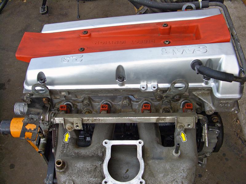 |
| 09.07.2006: Injectors |
|
Slide the injectors into their sockets and secure the fuel rail with two
screws.
|
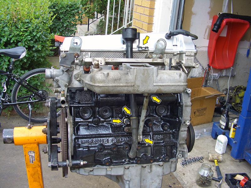 |
| 09.07.2006: Oil tube |
|
Screw in the oil pressure sensor (22 mm wrench), the upper part of the
dipstick tube and bolt on the intake manifold stay.
|
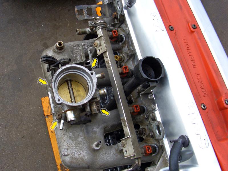 |
| 09.07.2006: Throttle body |
|
Lubricate the rubber gasket and install the throttle body.
|
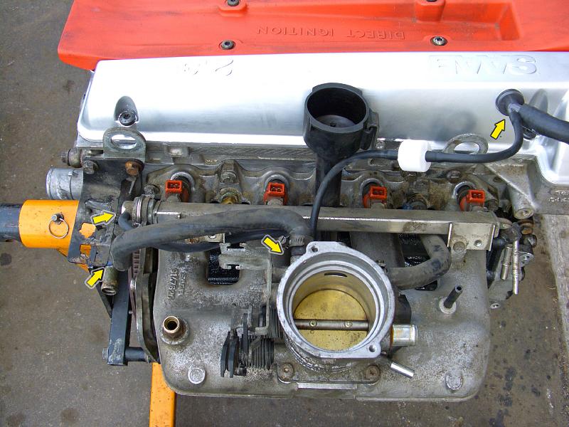 |
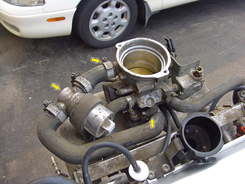
| 09.07.2006: Hoses |
|
Fit the vacuum hose to the fuel pressure regulator, and a hose with a check
valve from the vent nipple (the arrow on the valve should point to the
throttle body). Attach the throttle body warm-up coolant hoses.
|
 |
| 09.07.2006: IAC valve |
|
Install the idle air control valve (IAC) and connect its hoses to
the throttle body.
|
 |
| 09.07.2006: Wiring harness |
|
The wiring harness is held by two screws to the fuel rail. Take your time
fitting all the connectors. Luckily, they are colored, indexed and rather
hard to plug in incorrectly.
|
 |
| 09.07.2006: Temperature sender |
|
Attach the temperature sender and the crankshaft position sensor. Plug
them into the remaining connectors on the harness.
|
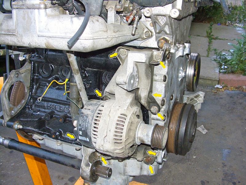 |
| 09.07.2006: Alternator |
|
Install the intermediate shaft bracket, the alternator
bracket (13 mm socket) and then two long bolts holding the alternator
(8 mm Allen).
|
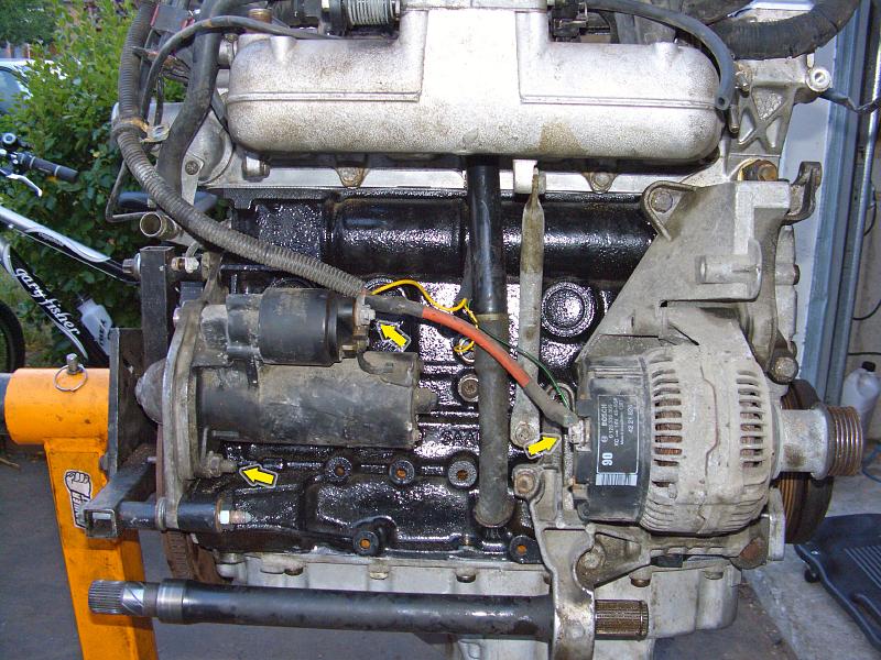 |
| 09.07.2006: Starter |
|
Attach the starter motor to the stud on the endplate. Connect the control
wires and the positive line from the battery.
|
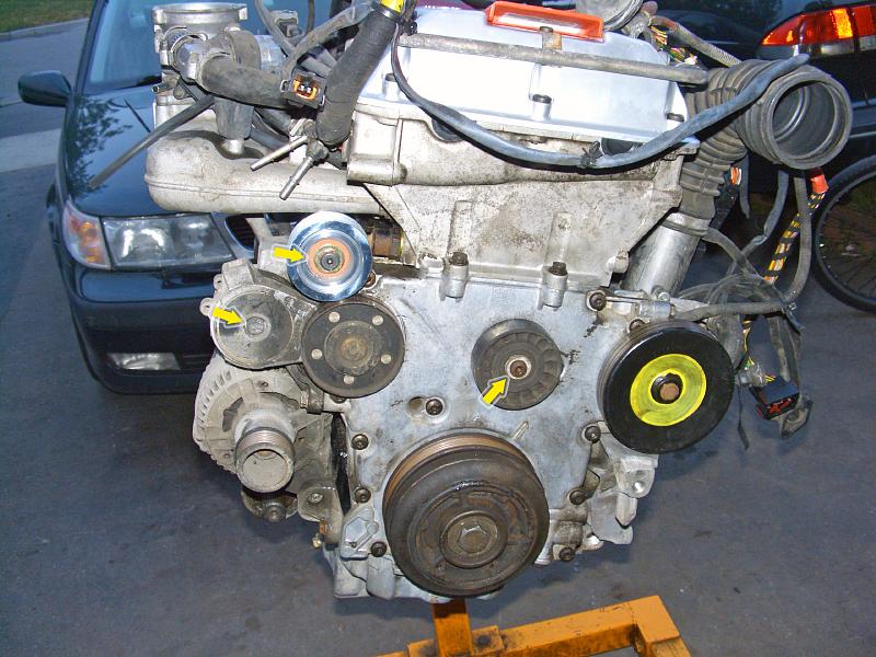 |
| 09.07.2006: Pulleys |
|
Install the belt tensioner (8 mm Allen) and the idler pulleys. The upper
idler pulley on this picture is the aluminium pulley by Wazee.
Proceed with engine installation.
|


