 |
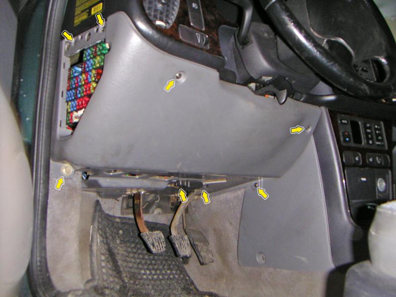
| 22.01.2006: Lower dash |
|
Remove the lower dash cover -- half a dozen Torx T25 screws and one 10 mm
bolt.
|
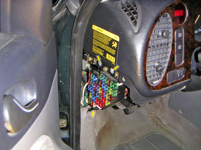 |
| 22.01.2006: Fuses |
|
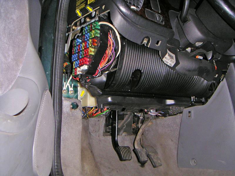
Three more T25 screws to remove the fuse panel.
|
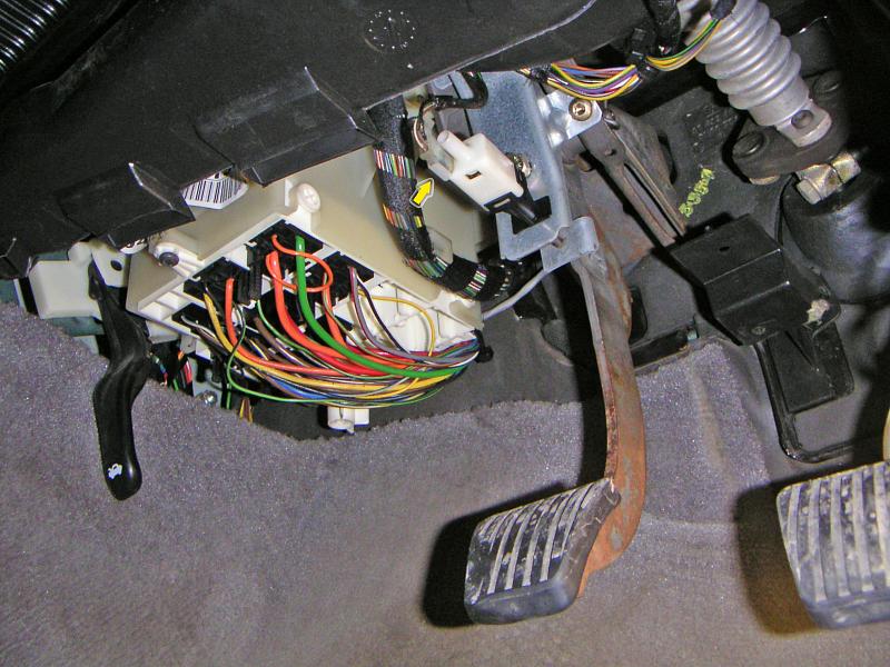 |
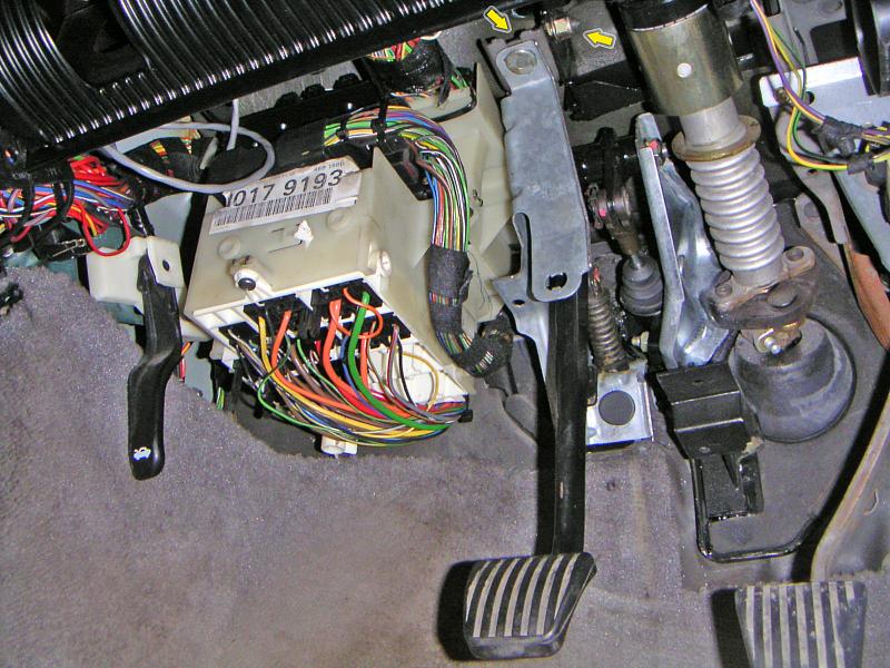
| 22.01.2006: Clutch pedal |
|
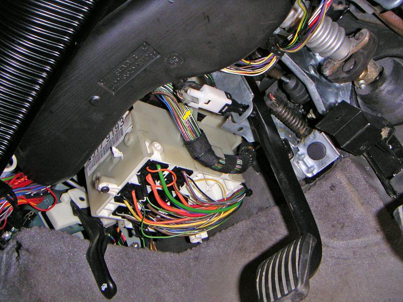
Remove both lower and upper air vents to get a better access to the
clutch pedal. Unplug the pedal position sensor.
|
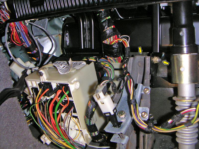 |
| 22.01.2006: Upper bolt |
|
Slacken the upper nut on top of the clutch pedal: it's completely
hidden from view, and you need a short wrench to get it moving.
The nut to the right of it does not need to be unscrewed, but it might
help to remove the pedal.
|
 |
| 22.01.2006: Fuse box |
|
Remove the plastic nut down below at the corner of the fuse box. Lift the
rubber strip along the firewall and unhook the other corner. Lift the
fuse box and move it aside as far as the wires allow.
|
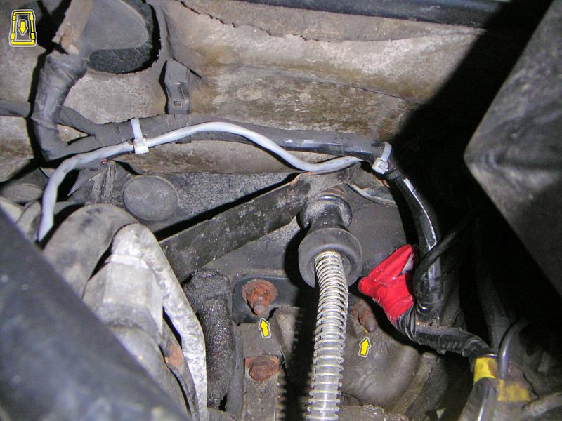 |
| 22.01.2006: Clutch cable |
|
Undo two nuts holding the clutch pedal to the firewall. Inside the car,
detach the clutch cable from the pedal, and remove the pedal completely.
From the outside, pull the cable out of the firewall.
|
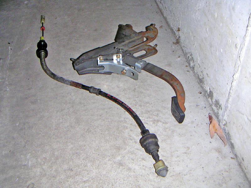 |
| 22.01.2006: Cable and pedal |
|
The clutch cable and old pedal on the floor.
|
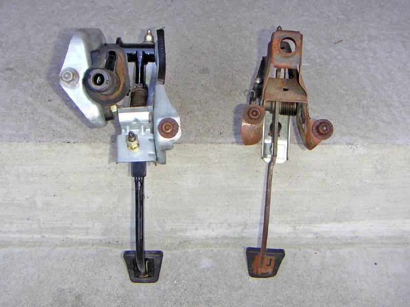 |
| 22.01.2006: New vs old |
|
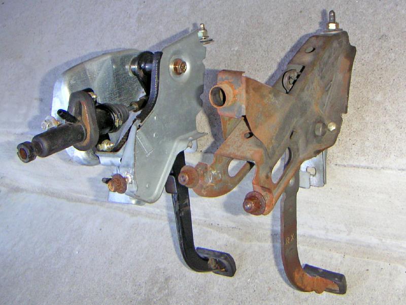
The old clutch pedal is just a lever on a mounting bracket.
The new one incorporates a hydraulic master cylinder.
|
 |
| 22.01.2006: New vs old |
|
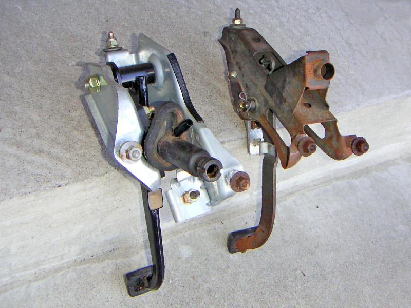
The master cylinder goes through the firewall in a location different
from the cable.
|
 |
| 22.01.2006: New vs old |
|
One of the mounting bolts for the new pedal is also in a different spot.
|
 |
| 22.01.2006: Drilling template |
|
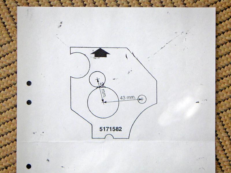
This is a drilling template from the Saab manual. The upper circle is
17 mm, while the lower is 35 mm. The mounting hole in the right is 9 mm.
|
 |
| 22.01.2006: Two templates |
|
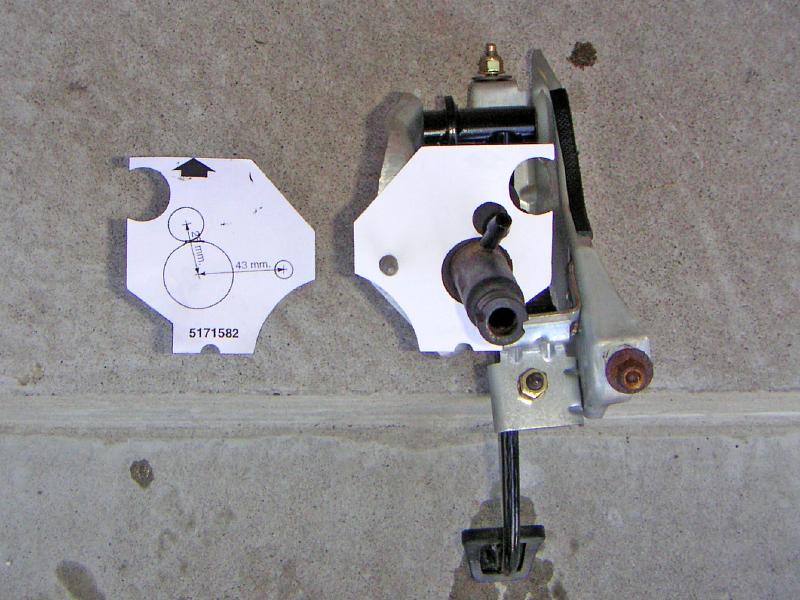
I made a second copy of the template to get a clear picture of the
cut-out usage.
|
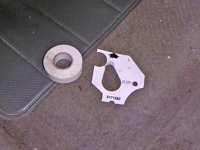 |
| 22.01.2006: Sticky tape |
|
The round holes are to be combined into an oval. The double-sided sticky
tape will be used to attach the template to the firewall.
|
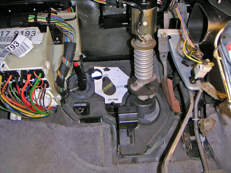 |
| 22.01.2006: Applied |
|
Attach the template making sure it fits the existing holes. Mark the
outside shape and peel it off.
|
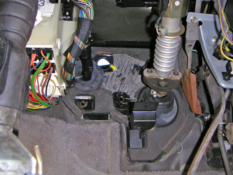 |
| 22.01.2006: Rubber cut |
|
Cut and remove the rubber insulation on the firewall.
|
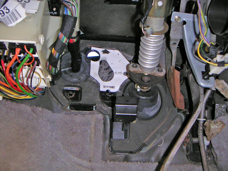 |
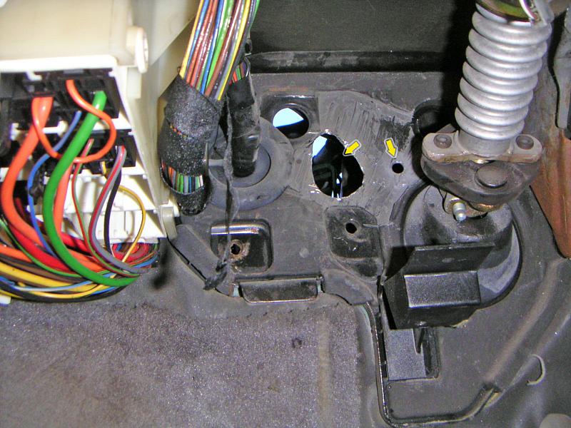
| 22.01.2006: Marking a hole |
|
Now that you've reached the metal, apply the template again and mark the oval
and the mounting hole.
|
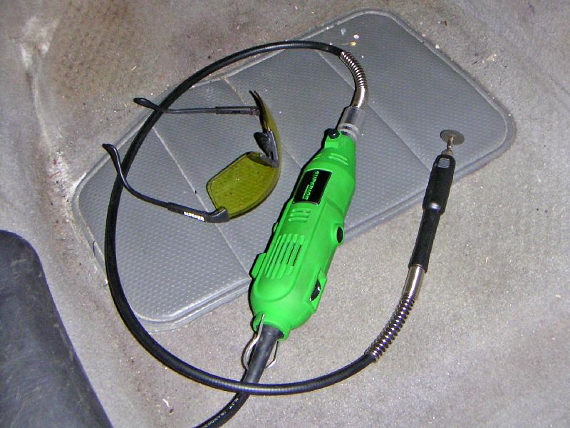 |
| 22.01.2006: Cutter |
|
Get a proper metal cutter. A rotary tool with a flexible extention or
a 90° adapter should work fine. Eye protection is a must.
|
 |
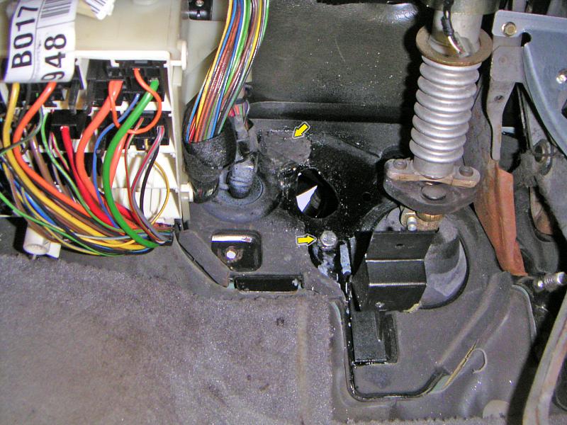
| 22.01.2006: Hole |
|
Half a dozen cutting discs later, and the oval is finished. The mounting
hole in the right is easy -- just start it with a thin drill bit
(e.g. 3 mm), and then do a second pass with a 9 mm.
|
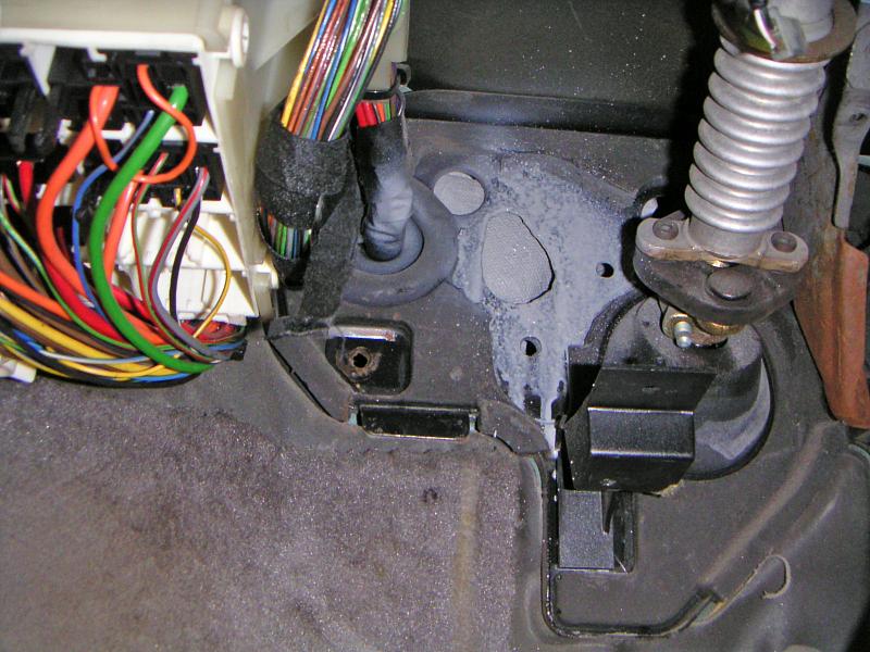 |
| 22.01.2006: Primed |
|
Sand and prime the cut-out to protect it from rust. Do the same
on the outer side of the firewall.
|
 |
| 22.01.2006: Painted |
|
Paint the surface. One of the old mounting holes is not needed anymore,
plug it with a short bolt and tighten the nut on the other side. Plug
the old cable hole too.
|
 |
| 22.01.2006: New pedal |
|
When fitting the new pedal, place a 2 mm washer under the bolt that goes
into the newly drilled mounting hole. Fit the upper mounting bracket
and tighten the nuts.
|
 |
| 22.01.2006: Master cylinder |
|
Tighten the nuts on the outside of the firewall.
|
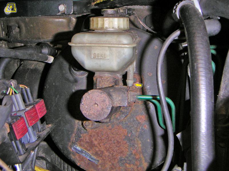 |
| 22.01.2006: Brake reservoir |
|
Cut the end of the downward pointing nipple on the brake reservoir,
about 3 mm should be enough. Catch the brake fluid that will leak out.
|
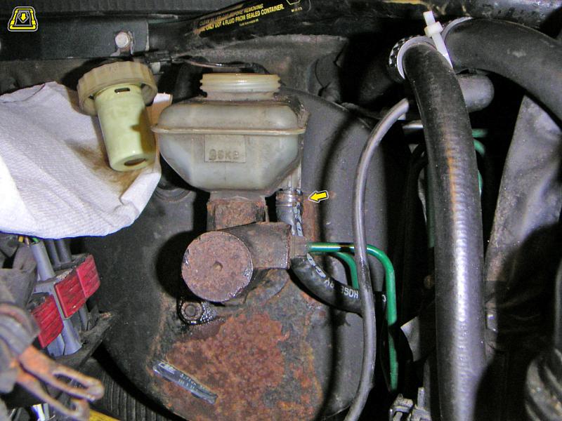 |
| 22.01.2006: Hose |
|
Attach a hose to the nipple and clamp it tight.
|
 |
| 22.01.2006: Hose |
|
Attach the other end of the hose to the upper socket on the
master cylinder. Clamp it as well.
|
 |
| 22.01.2006: Sensor |
|
Fit the air vents and attach the clutch pedal position sensor.
|
 |
| 22.01.2006: Fuses |
|
Install the fuse panel.
|
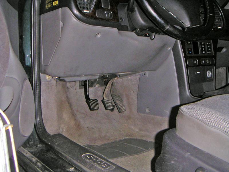 |
| 22.01.2006: Lower dash |
|
Put the lower dash cover back on. It's amusing how much the new
pedal stands out.
|
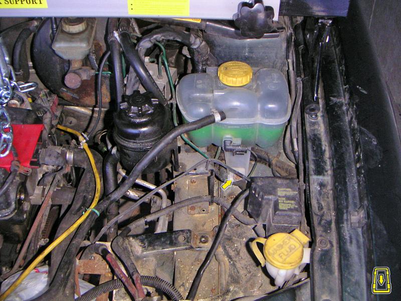 |
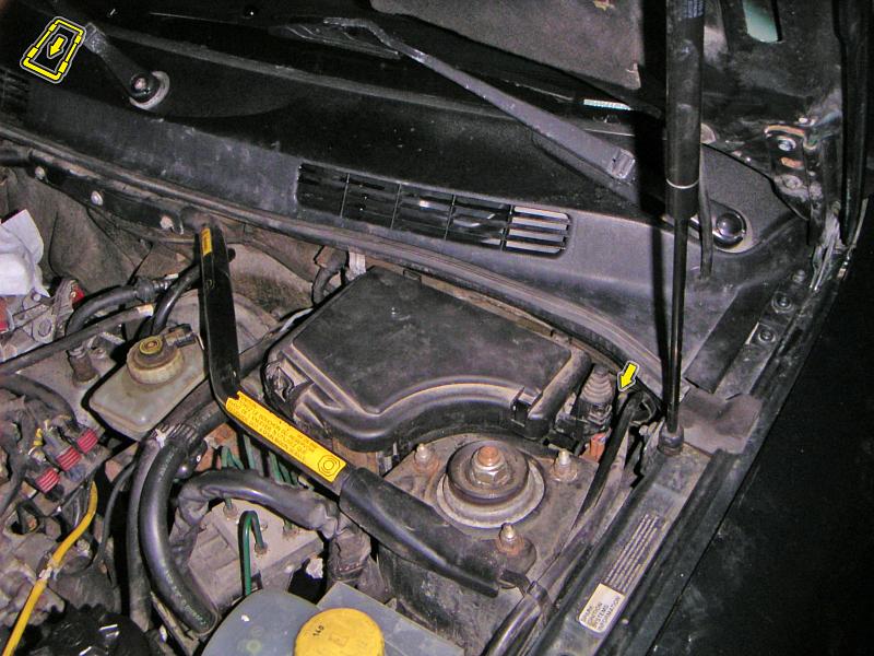
| 22.01.2006: Coolant tank |
|
Remove the nut holding the coolant expansion tank. Lift the tank.
|
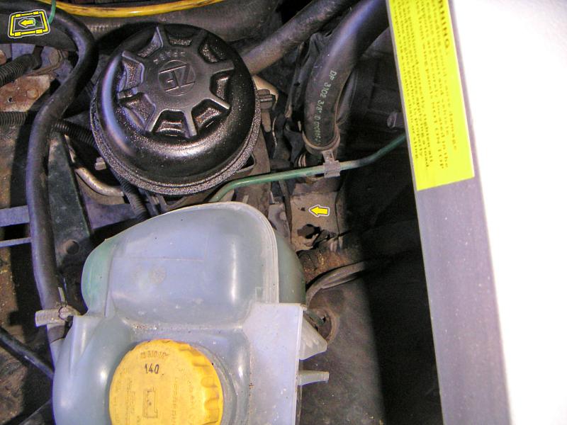 |
| 22.01.2006: Hole |
|
Drill a hole on the edge of the side member for a clamp that will hold the
clutch line.
|
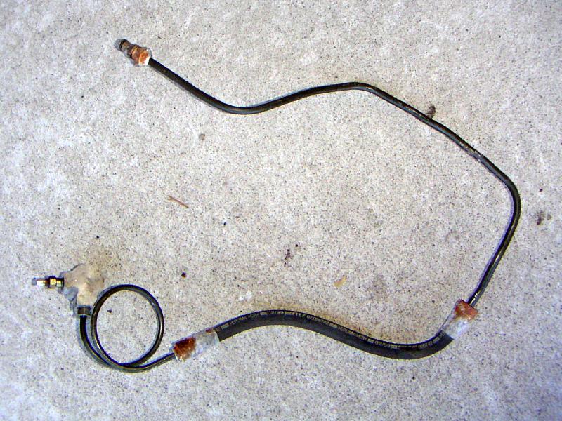 |
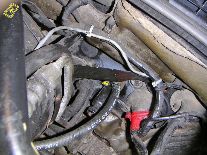
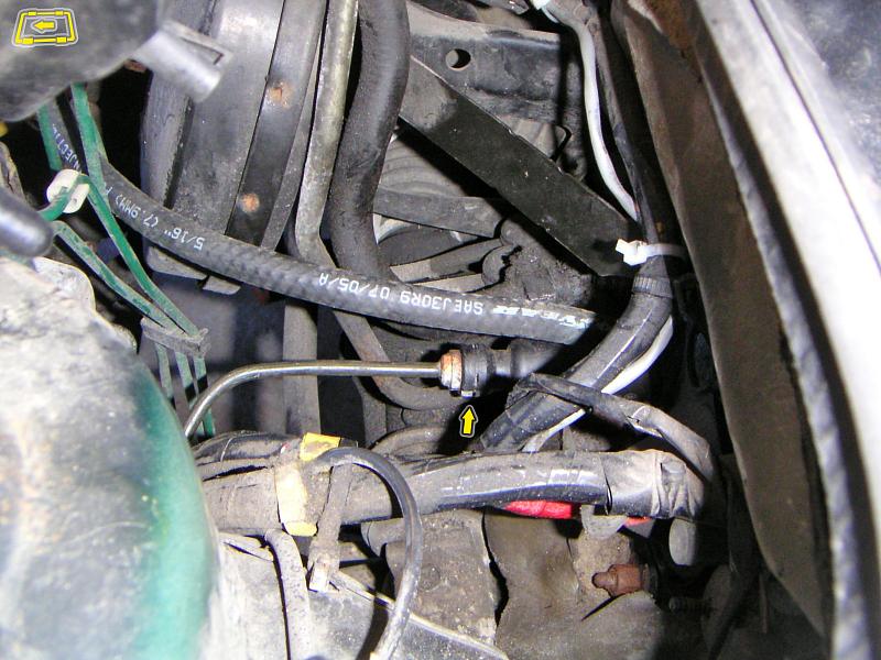
| 22.01.2006: Clutch line |
|
A new clutch line. The rubber section is there to accomodate the engine
movement. The 90° bend on the right is where the line will be clamped.
|
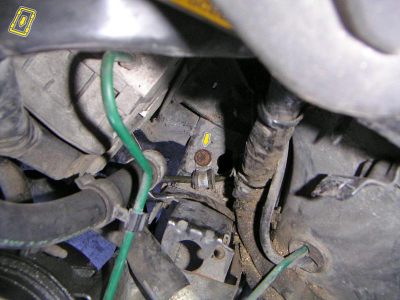 |
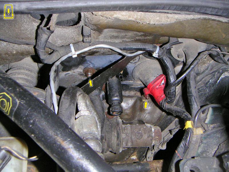
| 22.01.2006: Clamp |
|
Route the clutch line between the fender and the ABS unit bracket
and secure it with a clamp.
|
 |
| 22.01.2006: Master |
|
Plug the end of the clutch line into the master cylinder and insert
the locking clip.
|
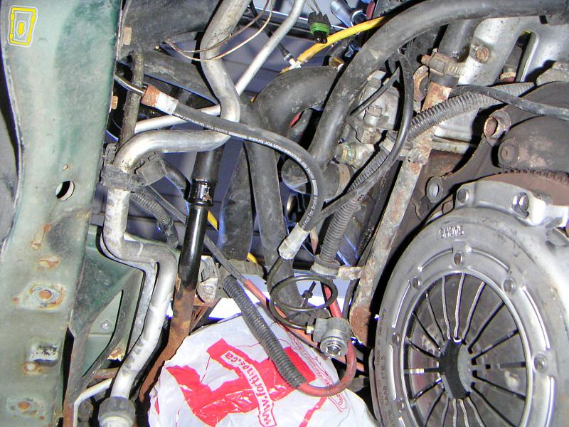 |
| 22.01.2006: Clutch line |
|
The other end of the clutch line will be attached to the slave cylinder
once the transmission is installed.
|


