 |
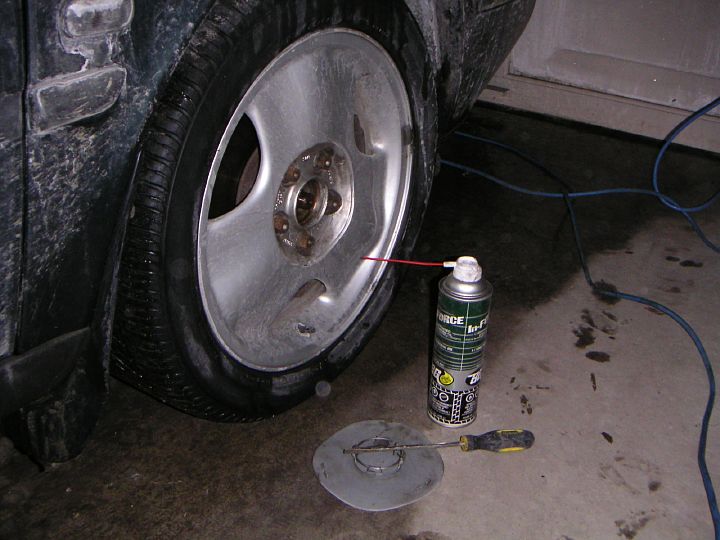
| 10.02.2005: Centre cap |
|
With the car still on the ground, remove the centre cap from the wheel
and spray the axle nut with a lubricant.
|
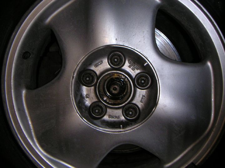 |
| 10.02.2005: Axle nut |
|
Here's a close-up of the axle hut. It might be a good idea to clean the
thread with a wire brush too.
|
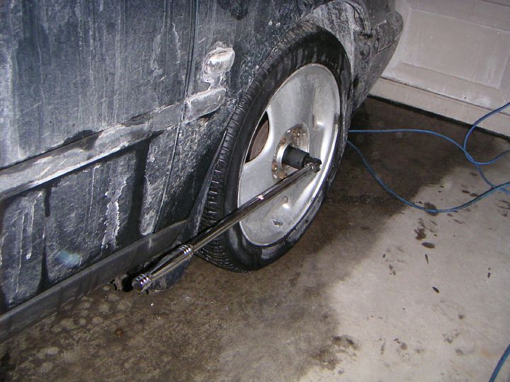 |
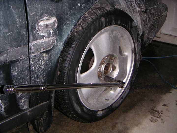
| 10.02.2005: Axle nut |
|
Loosen the nut using a 32 mm socket (a 1¼" will do too) and a
breaker bar.
|
 |
| 10.02.2005: Wheel nuts |
|
Loosen the wheel bolts too (you'll need a deep 17 mm socket for that).
|
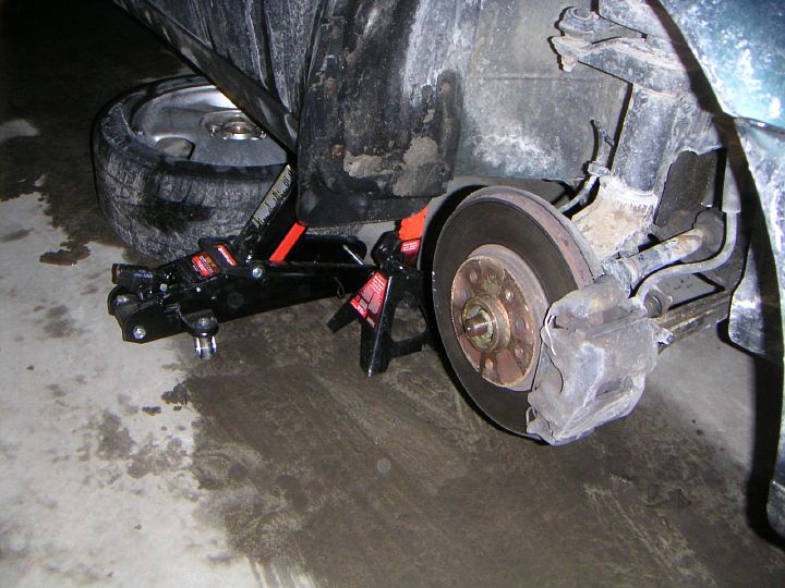 |
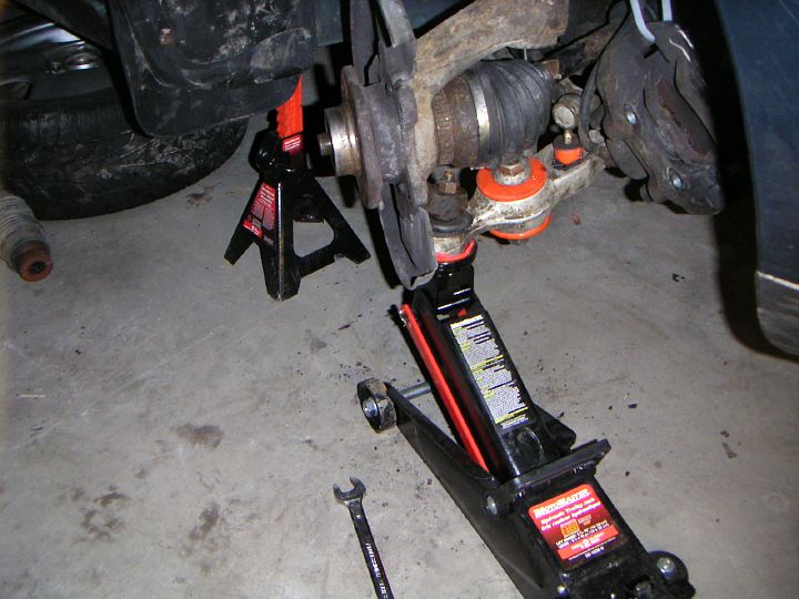
| 10.02.2005: Jacks |
|
Raise the car, put it on jack stands and take off the wheels. The car is
filthy: this is what Ontario roads do to your car in winter. I washed it
just a couple of days ago.
|
 |
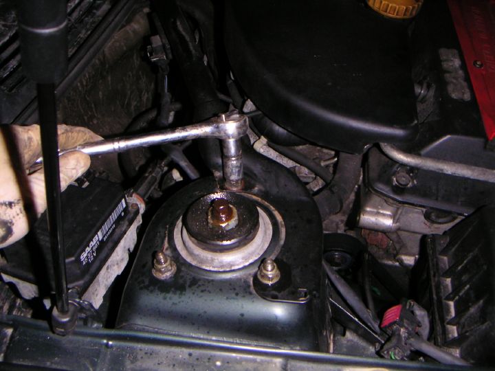
| 10.02.2005: Axle nut |
|
Remove the axle nut. Take your time spraying all other fasteners with
your favourite rust solvent.
|
 |
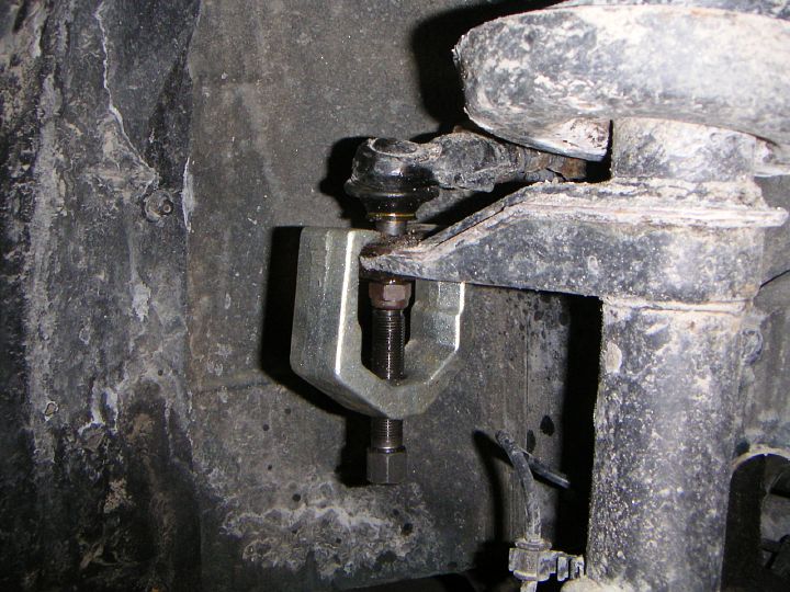
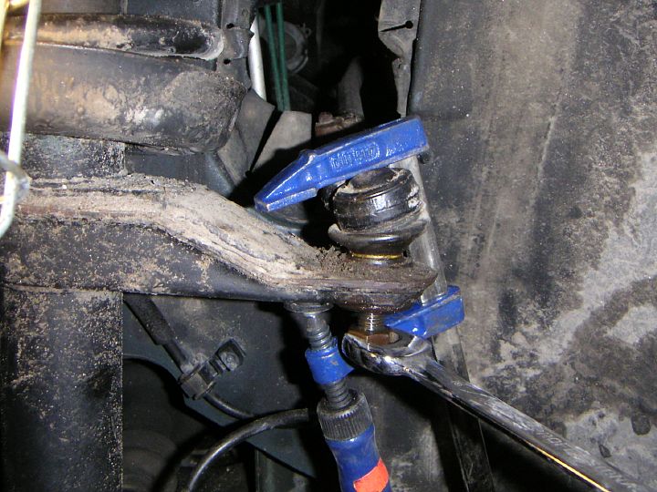
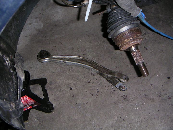
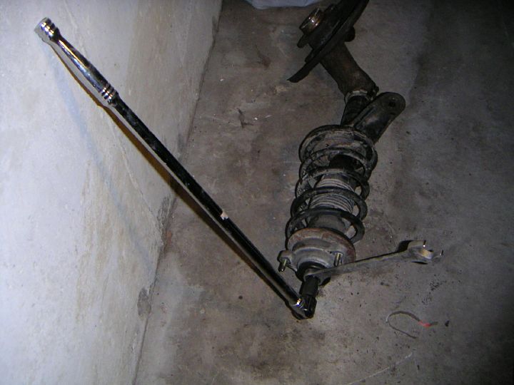
| 10.02.2005: Tie rod end |
|
Undo the tie rod end nut using an 18 mm socket. Remove the nut completely,
clean and lubricate the thread, and put the nut back on a few turns to
provide a base for the next step.
|
 |
| 10.02.2005: Gear puller |
|
Use a ball
joint separator or gear puller to push out the tie rod end.
If you didn't fully remove
the nut prior to that, and it gets stuck, there won't be enough friction
to turn the nut anymore, it will just spin in the ball joint.
Guess how I know that ;)
|
 |
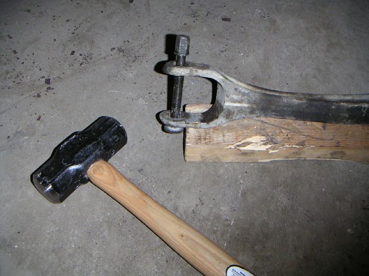
| 10.02.2005: Clamp |
|
If you were unfortunate enough to make this mistake, clamp the tie rod
end to the strut and unbolt the stuck nut. You will also need to use the
clamp when assembling the thing later.
|
 |
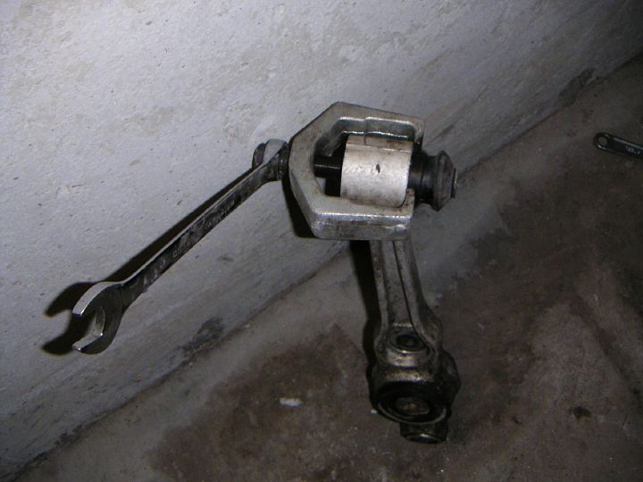
| 10.02.2005: Sway bar link |
|
Disconnect the sway bar link from the control arm. Use a 13 mm socket on
the nut below, and hold the top with a 11 mm open wrench. The left side
link on my car snapped when I tried to undo the nut (too much rust).
A new one was $50 at the dealer.
|
 |
| 10.02.2005: ABS sensor |
|
An engineer who decided to use tiny bolts with a 5 mm Allen head for ABS
sensors should be prosecuted. With this much rust, the head instantly
rounds off when you first attempt to unbolt it, and then snaps
completely when you try to finish the job with vice-grips. To avoid that,
undo the bolt that holds the sensor bracket instead: it's also a 5 mm Allen,
but its thread is not exposed to moisture.
|
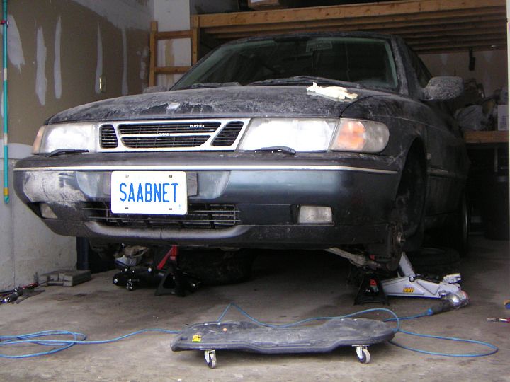 |
| 11.02.2005: The car |
|
This is the car sitting in the garage. Luckily, I didn't have to hurry
with finishing the work this time as we had the 9-5 to drive around.
|
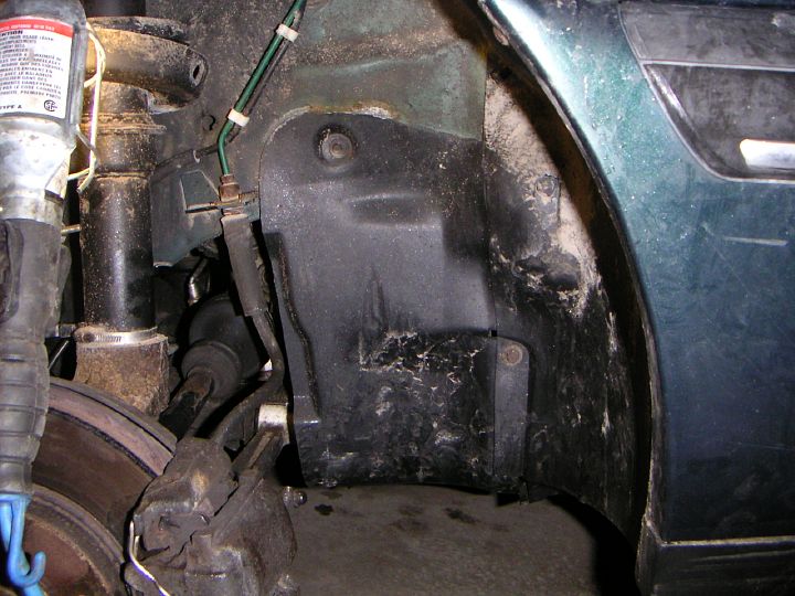 |
| 12.02.2005: Belt shield |
|
The plastic belt shield has to be removed in order to gain the access
to the inner control arm bolt. It is held by assorted screws with 8 mm and
10 mm hex heads.
|
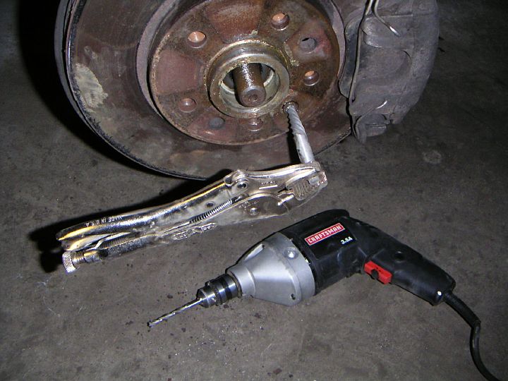 |
| 12.02.2005: Rotor screw |
|
The brake rotor index screw also has a 5 mm Allen head. Translation
from Rusty Saab: "with this much surface area, the bolt head will round off
in no time, so you will need a drill, a screw extractor, and a new $4 bolt
from the dealer."
|
 |
| 12.02.2005: Caliper bolts |
|
The caliper bolts take a 10 mm Allen key. Finally, a hex key big enough
not to strip the head.
|
 |
| 12.02.2005: Caliper |
|
Compress the caliper so it becomes free from the rotor, pull it away
and hang on a piece of wire to keep the brake line free from the caliper's
heavy weight.
|
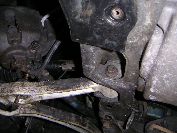 |
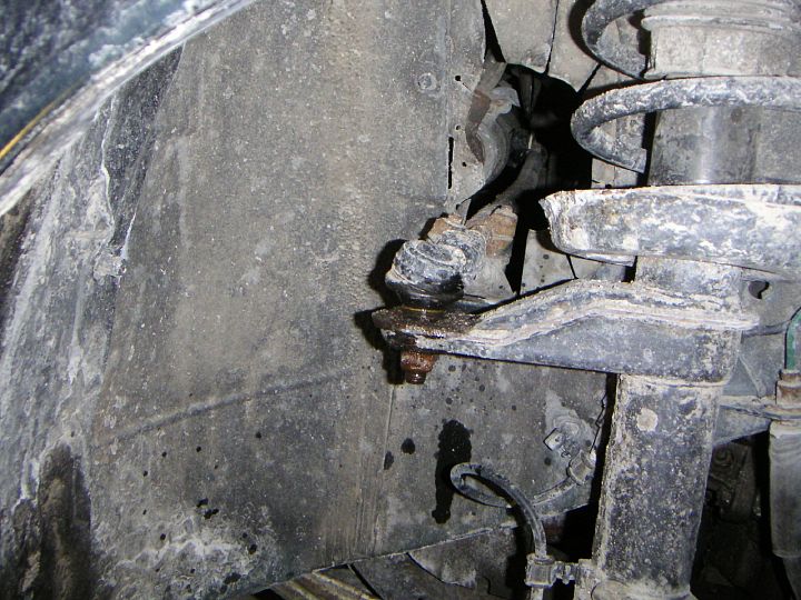
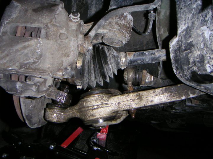
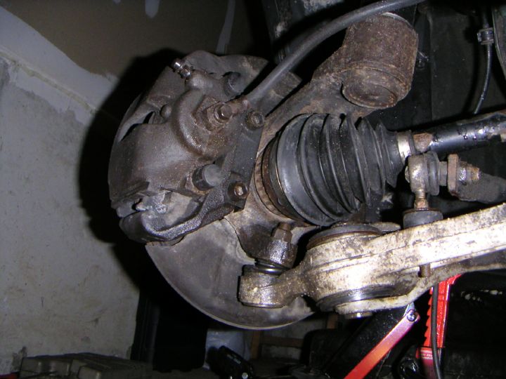
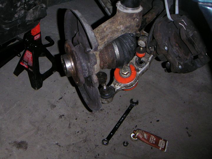
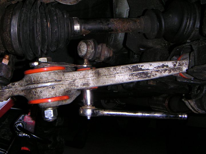
| 12.02.2005: Control arm |
|
The control arm bolt is accessible in the opening from below the
subframe (15 mm socket). I decided to take this route to skip the fight
with the ball joint on the car.
|
 |
| 12.02.2005: Stanchion arm |
|
The stanchion arm is bolted to the subframe from below (16 mm socket).
You don't really need to remove it completely, but I wanted to inspect the
bushing, and it's also easier to remove the old push nut when the arm is
off the car.
|
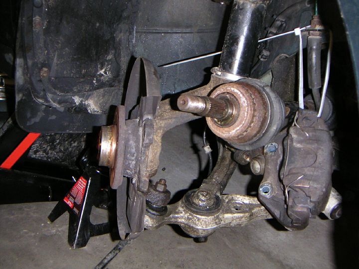 |
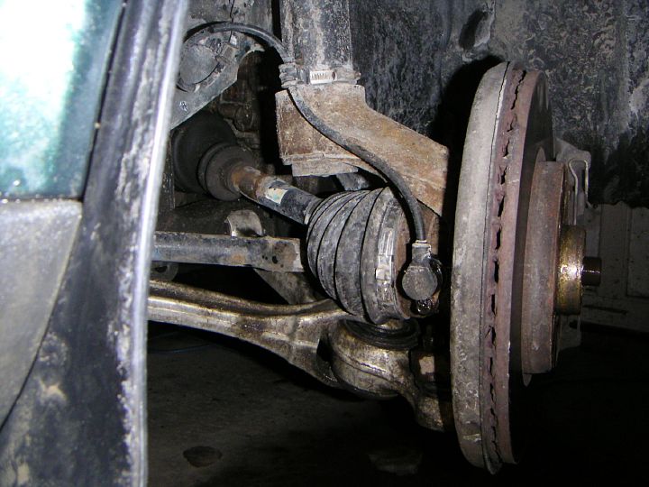
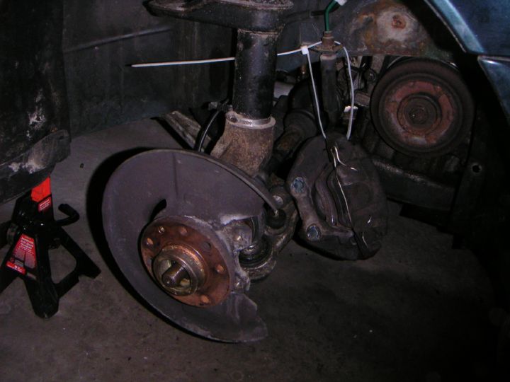
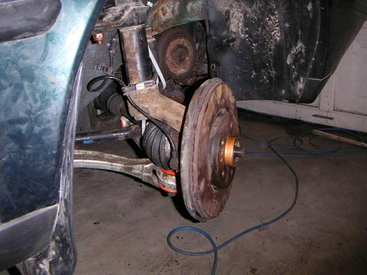
| 12.02.2005: Driveshaft |
|
With the control arm disconnected from the subframe, there's enough play
to pull the driveshaft out of the hub. Once the driveshaft is out
of the way, you can unbolt the stanchion arm from the outer bushing
(Torx T55).
|
 |
| 12.02.2005: Stanchion arm |
|
Move the stanchion arm away. The strut is now hanging on the upper
mount.
|
 |
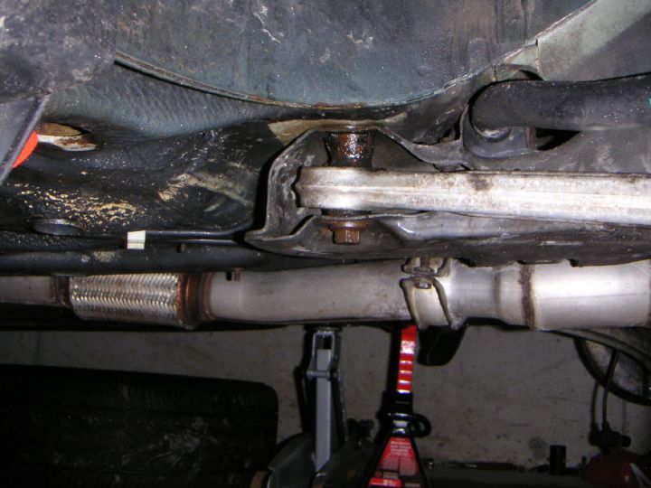
| 12.02.2005: Strut mount |
|
Carefully undo the strut mount nuts (13 mm socket) and remove the strut
assembly from the car.
|
 |
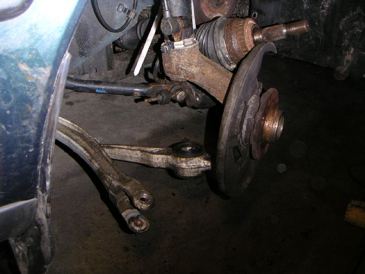
| 12.02.2005: Stanchion arm |
|
The stanchion arm on the ground. Now you have removed everything there is
to remove ;).
|
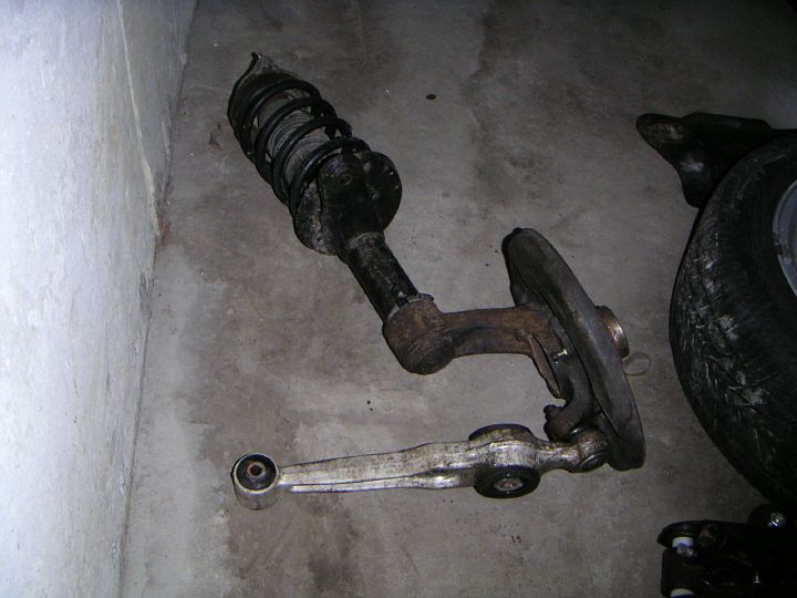 |
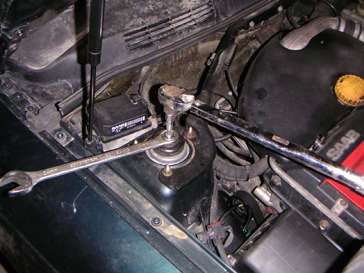
| 12.02.2005: Strut assembly |
|
With the strut assembly on the floor, it's easy to unbolt
and separate the ball joint. First, undo the nut (18 mm).
|
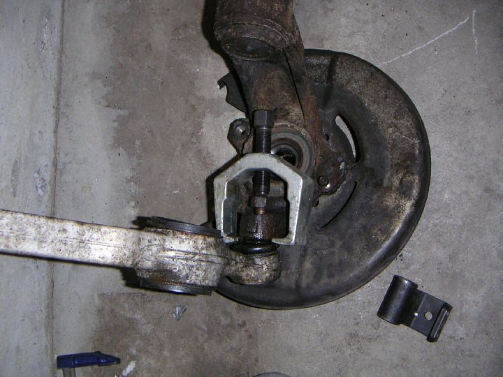 |
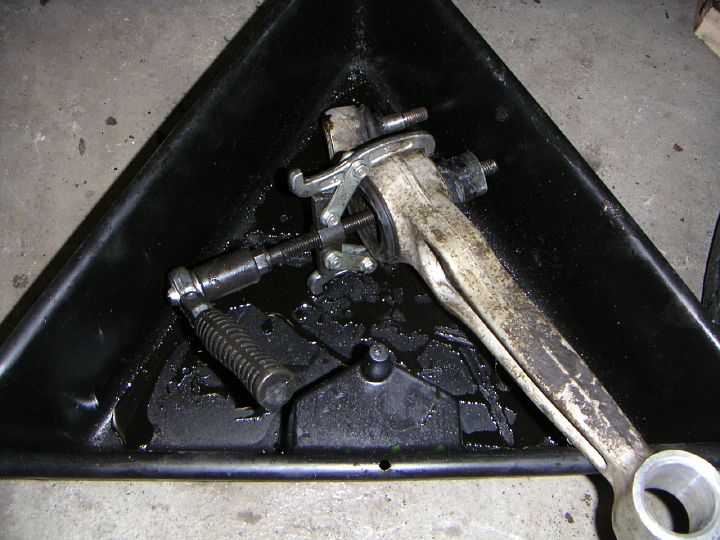
| 12.02.2005: Ball joint |
|
Then use a gear puller or a
screw-type
ball joint separator to break the
bond. The use of fork-type ball joint splitters is not recommended as they
often damage the rubber boot.
|
 |
| 12.02.2005: Top nut |
|
Loosen the retainer nut on top of the strut. You will need a 24 mm
wrench for the nut and a 11 mm socket to hold the damper rod. Another
alternative is to use an impact wrench to loosen the nut (the former
method does not work on 9-3s as they have different strut mounts and
the nut is harder to reach).
|
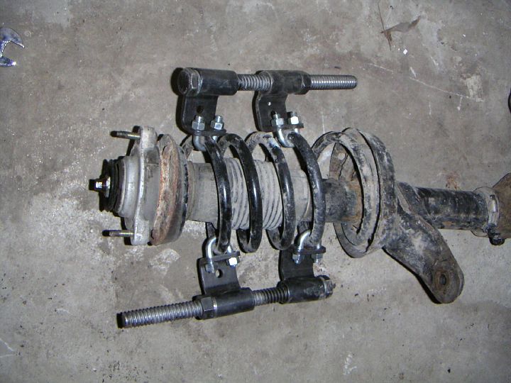 |
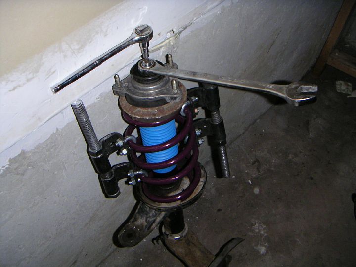
| 12.02.2005: Spring compressor |
|
Do not
remove the nut completely: the spring is under load, and releasing it
can cause an injury.
Attach a spring compressor tool and tighten it until the spring becomes loose
in the housing. Remove the top nut, the strut mount and other parts,
then carefully release the tension of the spring.
|
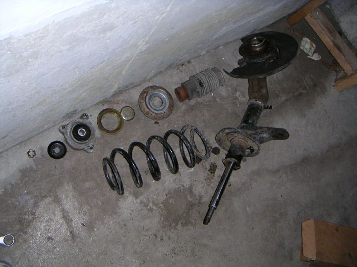 |
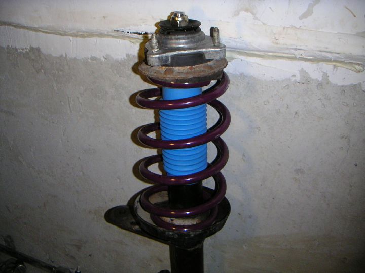
| 12.02.2005: Disassembled |
|
Clockwise: top nut (do not reuse it!), washer, strut mount, thrust
bearing, another washer, spring support, bump stop, strut with damper,
spring. Remember how the washers were fitted: the edges on the top washer
should point up, while on the bottom washer they should point down.
|
 |
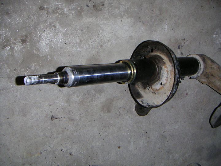
| 12.02.2005: Strut insert |
|
The strut insert is secured by a 60 mm sleeve nut. I didn't have anything big
enough, so I took it to the nearest mechanic. They put it in a vice and
used the biggest pipe wrench I've ever seen. Two minutes, and the job was
done, didn't even take the money.
|
 |
| 12.02.2005: Push nut |
|
The old push nut in the stanchion arm is no longer needed if you're
installing the bushings
from Taliaferro, which come with a bigger bolt. A few blows with a
heavy hammer will do the job.
|
 |
| 12.02.2005: Inner bushing |
|
The inner control arm bushing is a simple rubber piece with a metal insert,
so you can easily press it out with a gear puller.
|
 |
| 12.02.2005: Outer bushing |
|
The outer bushing can also be pressed out, just use a larger gear puller.
This bushing is of a hydraulic type, so bring a pan to catch the oil.
|
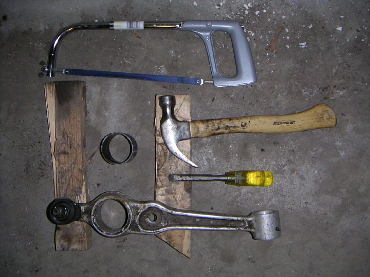 |
| 12.02.2005: Sleeve |
|
The metal sleeve of the outer bushing can be pressed out if you have a press.
If you don't, you can saw cut the sleeve and remove it with a chisel.
This will destroy it though, but who cares, we have a box full of
nice new poly bushings ;)
|
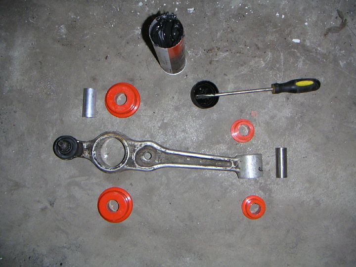 |
| 13.02.2005: Bushings |
|
The new bushings are a two piece design with a metal insert in the middle.
Prepare some silicone/moly grease to lubricate them.
|
 |
| 13.02.2005: Bushings |
|
The bushings are very snug, but you don't need a press to put them in.
Most of the job can be done with your bare hands with a little help
from a rubber mallet.
|
 |
| 13.02.2005: Arms |
|
Put the control and stanchion arms back on, but don't tighten the bolts
yet. Move the driveshaft out of the way and connect the arms at the
outer bushing.
|
 |
| 13.02.2005: New bolt |
|
Insert the new bolt that comes with the bushings and tighten it to 120
ft-lbs using a pair of 24 mm wrenches. After that tighten the bolts that
attach the arms to the subframe. Control arm: 85 ft-lbs, stanchion arm:
78 ft-lbs plus 90°.
|
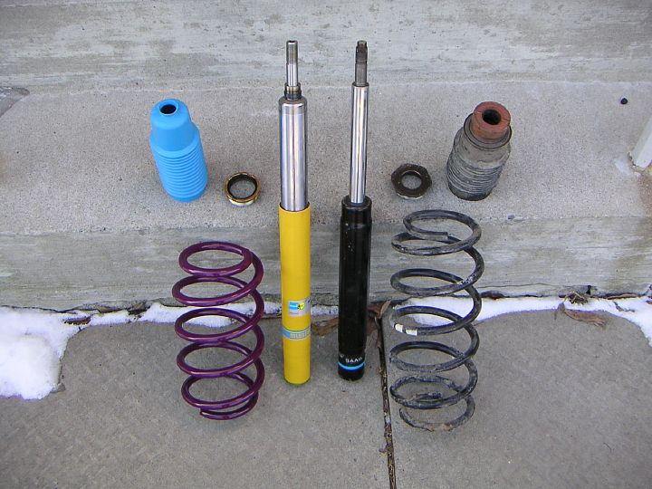 |
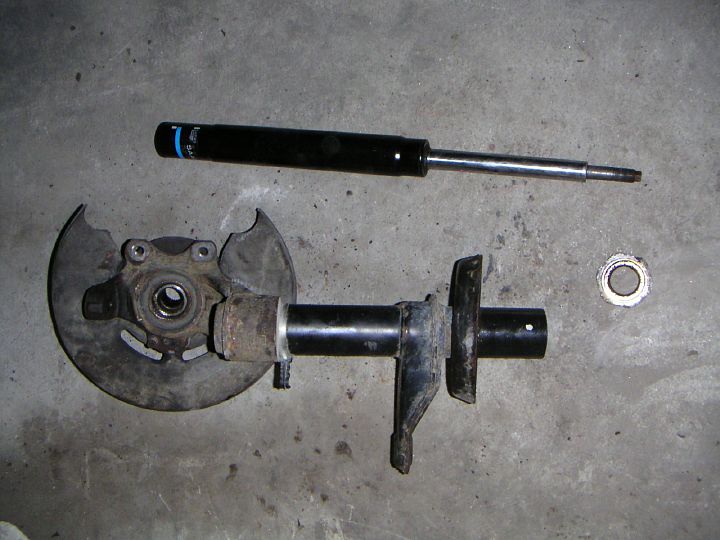
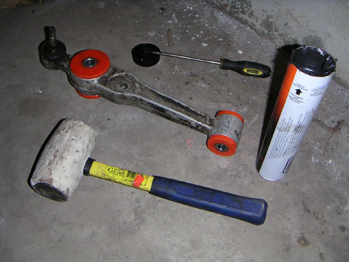
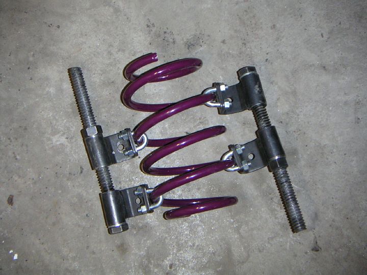
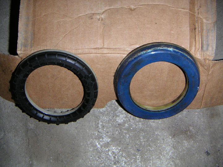
| 13.02.2005: New vs old |
|
Intrax springs have one coil less than the original, so they are
more than an inch shorter, but also stiffer. Bilstein dampers are only
a few millimetres shorter, but look much more serious. They come with their own
dust shield, which does not include a bump stop (this is by design). The
sleeve nut is also different.
|
 |
| 13.02.2005: Strut insert |
|
Here's the new damper fitted into the strut. I didn't have a torque wrench
that goes up to 160 ft-lbs, so I just put some loctite on the threads and
tightened it as hard as I could.
|
 |
| 13.02.2005: Spring |
|
A spring has to be compressed before it's put back on.
|
 |
| 13.02.2005: Thrust bearings |
|
Here's a new SKF thrust bearing vs whatever was on the car before. You
can see the damage on the body of the old bearing. Just a bit more, and it
would've split in half.
|
 |
| 13.02.2005: Assembling |
|
I used the original spring support and washers, but replaced strut mounts
and bearings. The new top nut that came with Bilstein dampers is the same
size as the original, but the grip on top of the rod is different, you
need a 7 mm Allen key for it.
|
 |
| 13.02.2005: Strut complete |
|
Make sure the spring fits both top and bottom supports correctly, with the
end of the coil against the spring stops. The top nut should be secured
well enough, but not yet to the spec, you'll need to do that later.
|
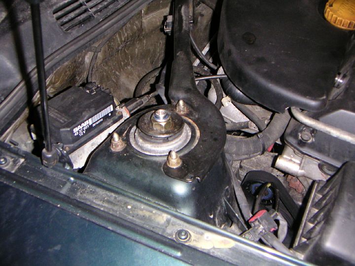 |
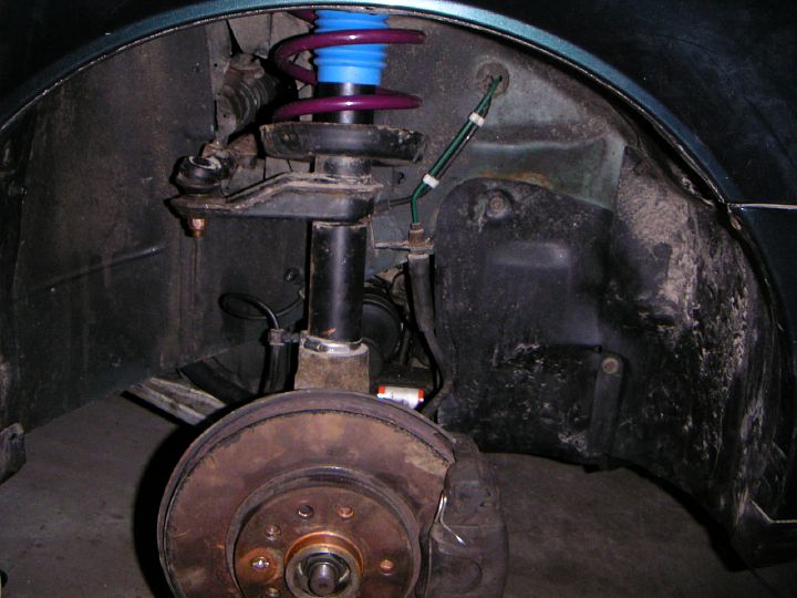
| 14.02.2005: Strut mount |
|
Fit the strut on the car and put the strut mount nuts on. Note that the
rearmost nut has a washer, while the other two don't. Tighten the nuts
alternately at 13 ft-lbs (13 mm socket).
|
 |
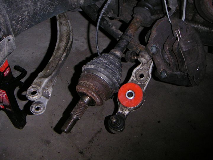
| 14.02.2005: Driveshaft |
|
Tilt the strut and insert the driveshaft into the hub. Fit the top washer
and bushing onto the sway bar link. Prepare a new ball joint nut (do not
reuse the old one).
|
 |
| 14.02.2005: Ball joint |
|
Insert the ball joint rod into the strut and put the nut on. Jack up the
base of the strut to force the ball joint in and prevent it from spinning.
Tighten the nut to 55 ft-lbs (18 mm wrench).
|
 |
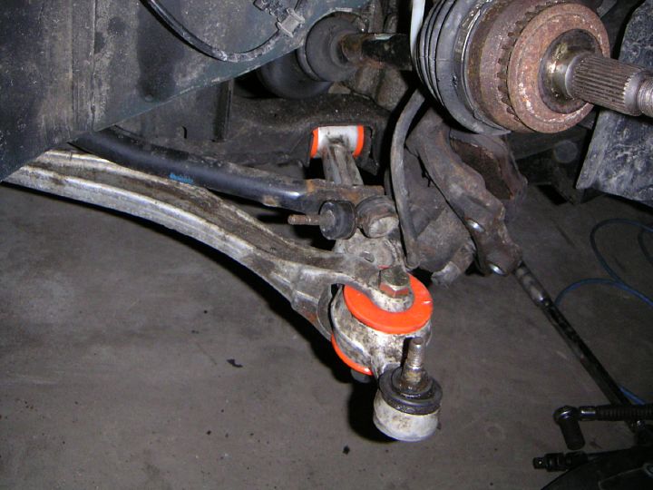
| 14.02.2005: Tie rod end |
|
Clamp the tie rod end and tighten the nut to 45 ft-lbs (18 mm socket).
|
 |
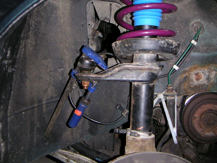
| 14.02.2005: Sway bar |
|
Put the lower bushing and washer on the sway bar link. Use an 11 mm open
wrench to hold the link at the top end, and a 13 mm wrench to tighten the
nut (8 ft-lbs)
|
 |
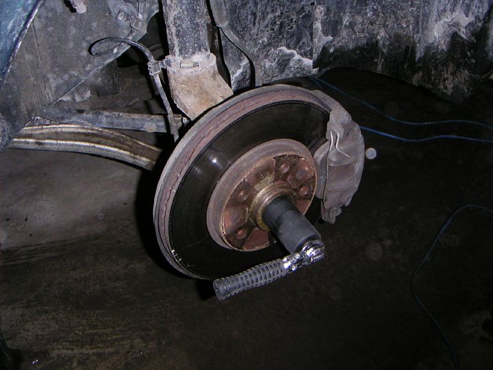
| 14.02.2005: Brakes |
|
Fit the ABS sensor and the brake rotor. Clean the hub before fitting the
rotor and apply some anti-seize to the hub and the rotor index screw.
Do not tighten the screw too much, unless you want to drill it out again.
|
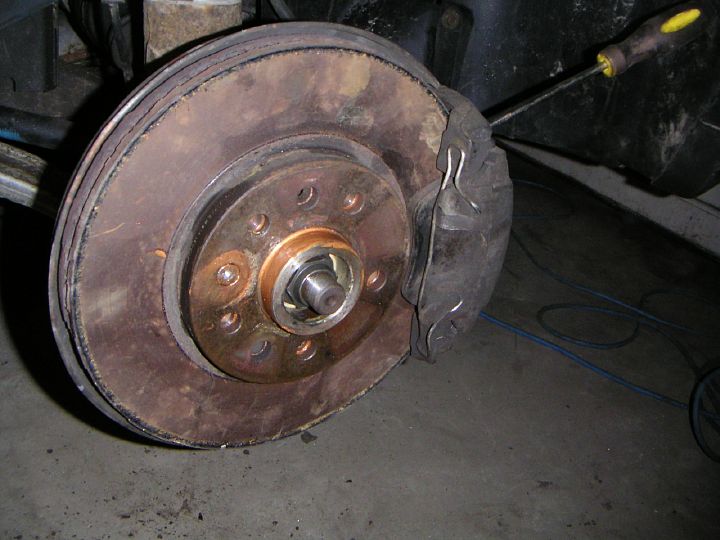 |
| 14.02.2005: Caliper |
|
Put the brake caliper back on, apply some loctite to the bolts and
tighten them to 87 ft-lbs (10 mm Allen key). Bolt on a new hub centre
nut (do not reuse the old one), but do not tighten it completely yet.
Stick a screwdriver into the rotor to prevent it from spinning.
|
 |
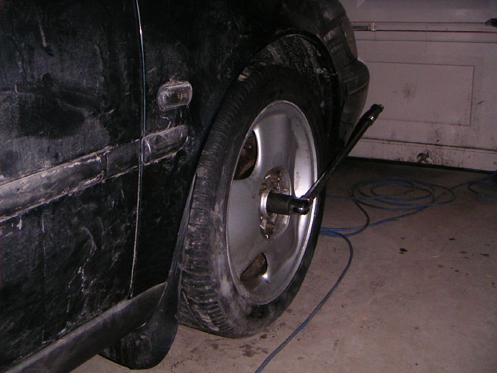
| 14.02.2005: Strut |
|
Attach the belt shield. Fit the wheels and tighten the bolts to 84 ft-lbs.
Lower the car to the ground.
|
 |
| 15.02.2005: Hub centre nut |
|
The hub nut (32 mm) should be tightened at 214 ft-lbs. I don't have a
torque wrench that goes that high, but 140 lbs of my weight applied to a
foot-and-a-half long breaker bar should work out about right.
|
 |
| 15.02.2005: Final_touch |
|
With the wheels on the ground, tighten the upper nut on the damper to 66
ft-lbs (24 mm wrench and a 7 mm Allen key). Congratulations, you have just
finished rebuilding your front suspension!
|


