|
|
The stereo head unit on a 1994-1998 Saab 900 does not have a CD player,
which is a bit strange for an entry luxury car of the mid-90s.
However, it does support Clarion C-Bus CD changers. Just plug and play.
I went on eBay and bought a Clarion RDC605 CD changer for $52.
Plugged it in... and it didn't play. Here are the symptoms:
- the changer loads the cartridge and checks every slot for CDs;
- when you select "CD" on the head unit, the changer attempts to select
the first available CD;
- the SID displays
CD1 WAIT
for a few seconds, and then switches to the radio;
- subsequent attempts to press "CD" on the head unit result in a brief
message
CD1 TRK 01
and then the unit switches back to radio again.
If you take off the cover and watch the changer trying to load a CD, you
discover that it would indeed try to pull a CD from the cartridge, load it
into the player, and then do it again, and again, and then stop after a few
more attempts.
|
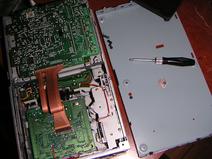 | | 22.12.2004: 1. Opened | |
When I opened the changer, a small piece of PCB fell out of the box.
You can see it below the screwdriver, it has a tiny contact switch on it.
The circuits were obviously torn.
| 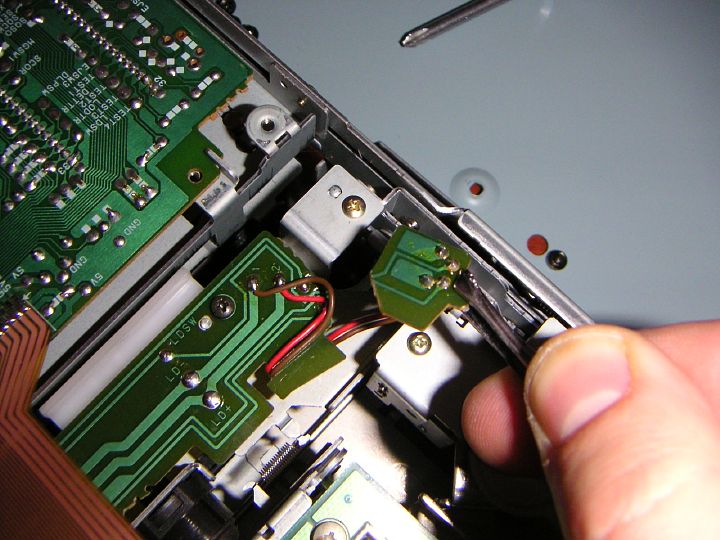 | | 22.12.2004: 2. Broken part | |
Here's where the switch is supposed to be. Every time a changer loads
a CD, a small metal arm hits the switch and signals the drive to stop the
movement. I find this to be a poor design, as the edge of the PCB is under
a stress every time the drive loads, and the board is only a few millimeters
wide at this location (there's a cut-out to let the wires through).
| 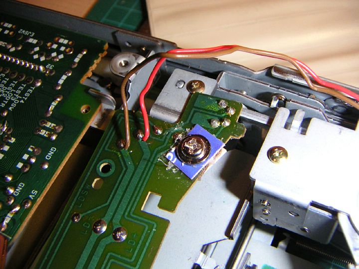 | | 22.12.2004: 3. Reinforced | |
I glued two pieces of plastic on either side of the board and tightened
this "band-aid" with a screw to reinforce the joint. Note the tab on the
right side of the board (see the next picture).
| 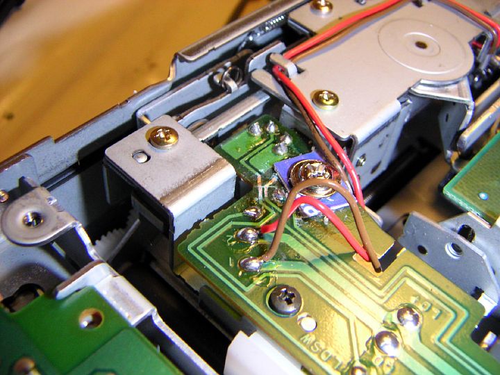 | | 22.12.2004: 4. Assembled | |
The tab on the right side goes into an opening in the frame to keep the board
steady. However, there's still a gap between the board and the frame, so
the metal arm that's hitting the switch would still bend the board and
eventually break it again.
| 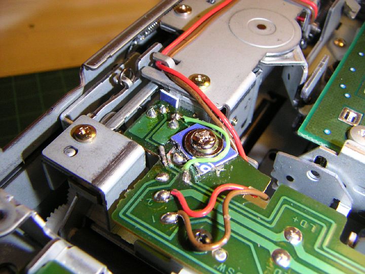 | | 22.12.2004: 5. Finished | |
Here's the finished assembly with an extra bump stop to fill the gap and
the wires soldered on to restore the broken connections. The changer
works now.
|
[return to index]
|
|