 |
| 09.10.2005: Two turbos |
|
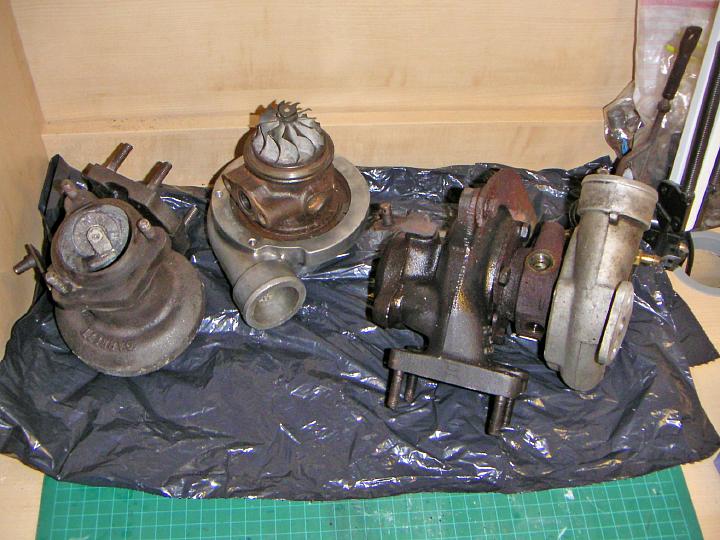
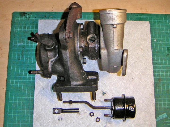
These are the two turbos I'm going to use. One has damaged wheels and
incredibly worn seals, while another has a cracked exhaust housing but
good internals. I'm hoping to combine them into one working unit.
|
 |
| 09.10.2005: Donor No 1 |
|
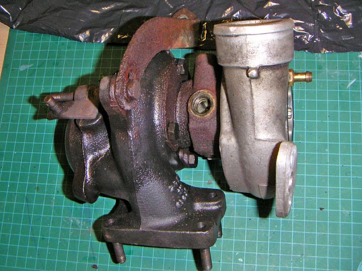
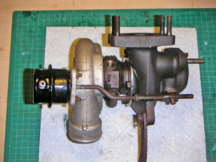
A close-up of one of the turbos. This one came from a 1999 9-3. The
wastegate actuator has been removed earlier.
|
 |
| 09.10.2005: Bolts |
|
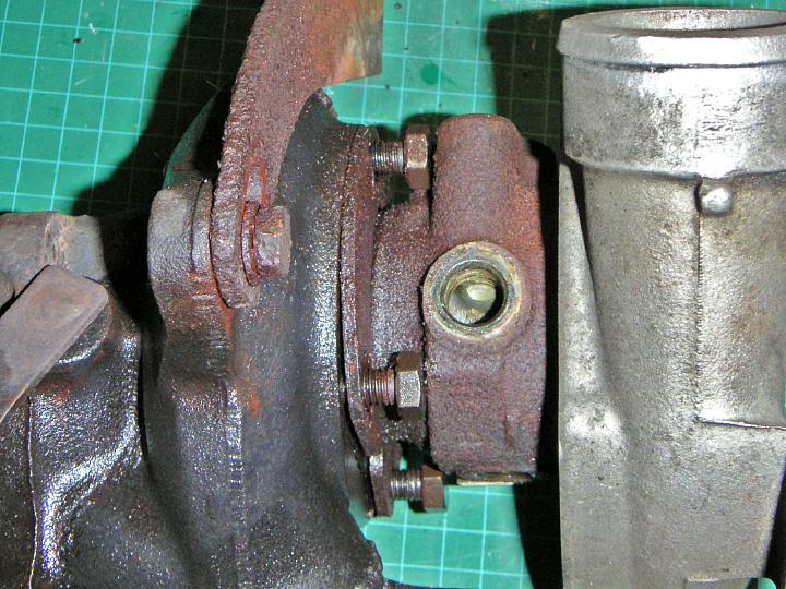
Undo the bolts on the exhaust housing using a 13 mm spanner. The bolts
are conveniently located so they can be used to press the housing off
the turbo.
|
 |
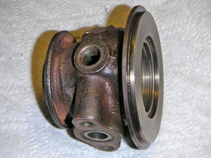
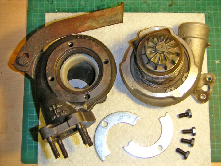
| 09.10.2005: Exhaust housing |
|
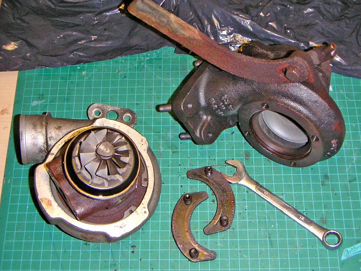
When using the bolts to force the housing off, do it very carefully, half
a turn at a time. Make sure it is coming off evenly and not jamming the
turbine wheel.
|
 |
| 09.10.2005: Snap ring |
|
The compressor housing is secured with a big snap ring, you need large
pliers for that.
|
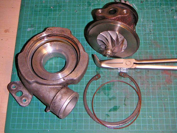 |
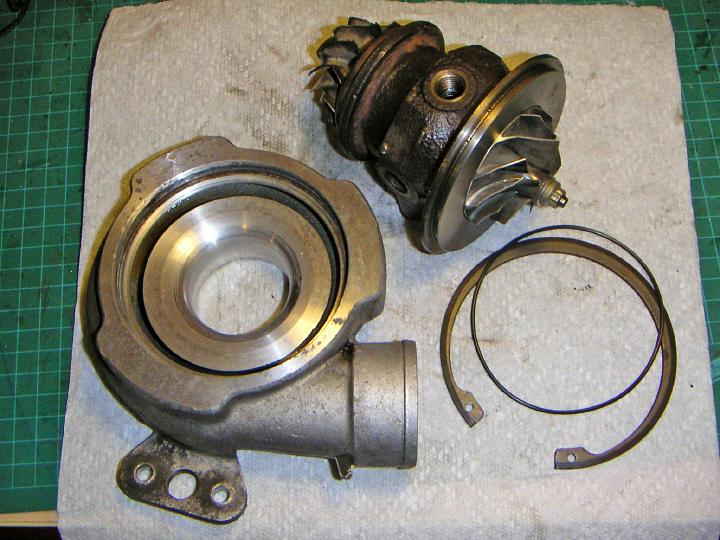
| 09.10.2005: Compressor housing |
|
The snap ring takes a few moments to wrestle, and then you can remove
the compressor housing... carefully.
|
 |
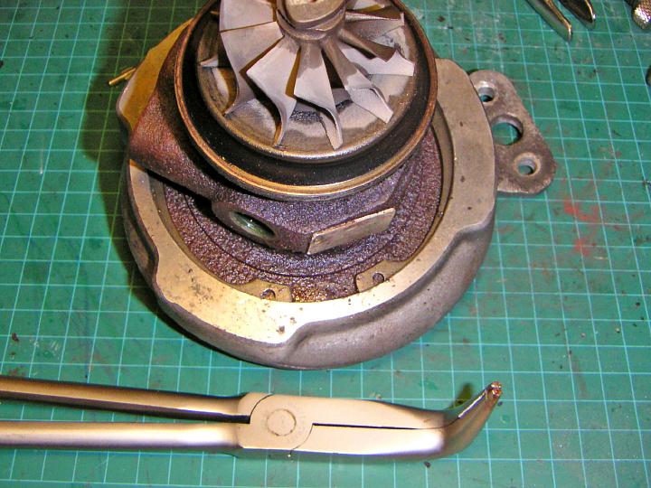
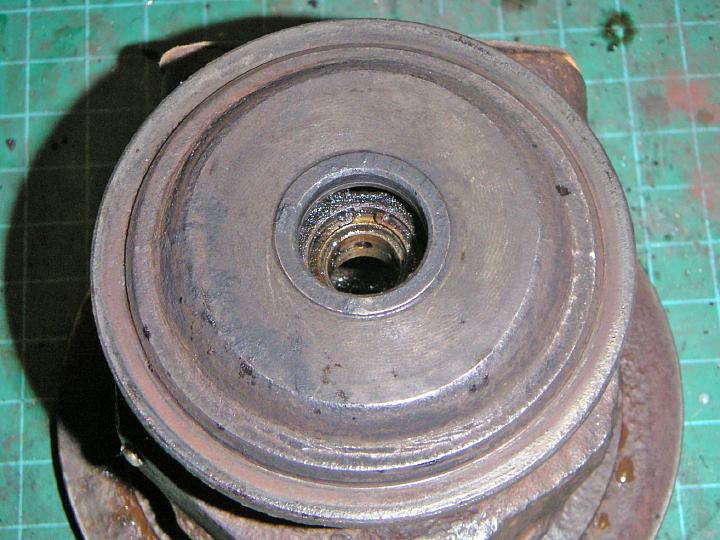
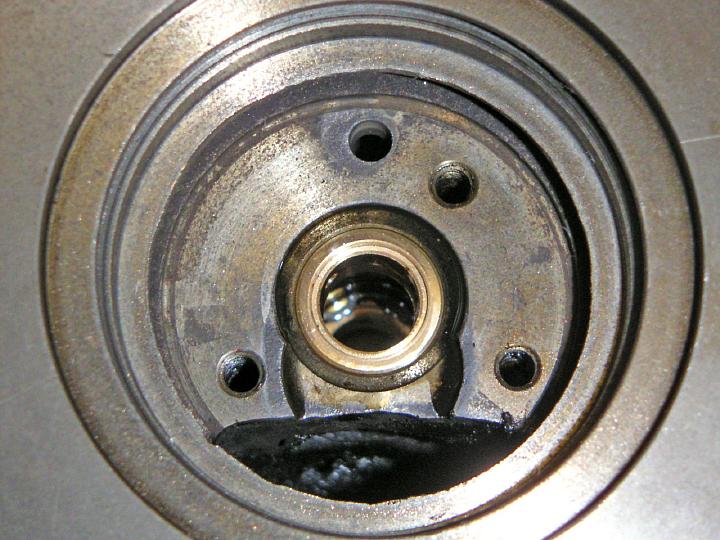
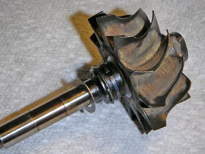
| 09.10.2005: Shaft play |
|
This shot illustrates the enormous amount of shaft play on one of the
turbos. The thrust bearing was completely destroyed, so the turbine ate
into the backing plate and grind itself down over 2 mm.
|
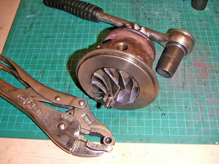 |
| 09.10.2005: Nut |
|
Grab the shaft nut with vise-grips and use a six-point 14 mm wrench on
the turbine end to undo the nut. Remember, the nut has a LEFT HAND thread.
|
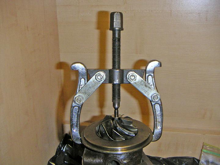 |
| 09.10.2005: Gear puller |
|
The compressor wheel might just come off, but most likely you'll have to
use a gear puller to press it off.
|
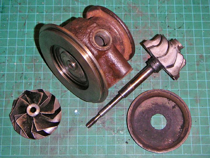 |
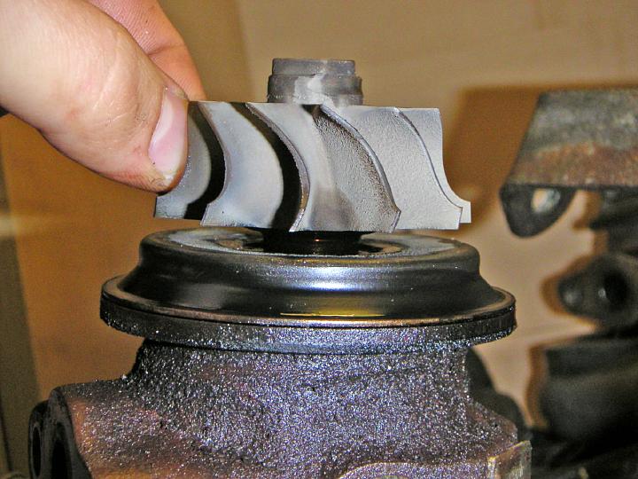
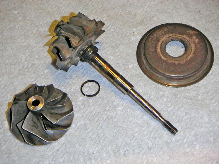
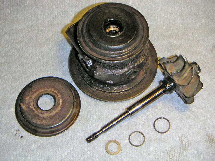
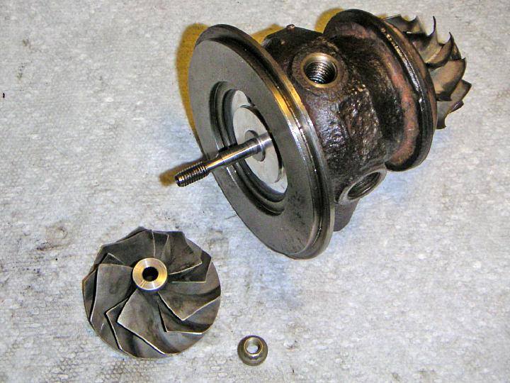
| 09.10.2005: Wheels removed |
|
Before pulling the wheels off, even before touching the nut on the shaft,
mark the position of the wheels relative to each other. You'll have to
assemble them in the exact same position later to preserve the balance.
|
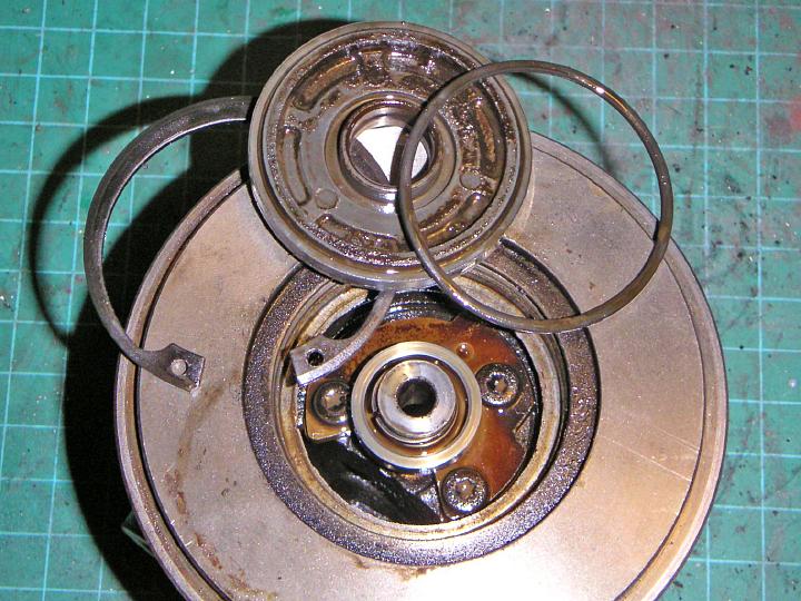 |
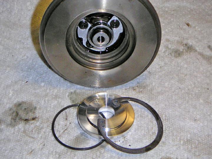
| 09.10.2005: Sealplate |
|
The sealplate is held by another snap ring, and there's a rubber ring
underneath.
|
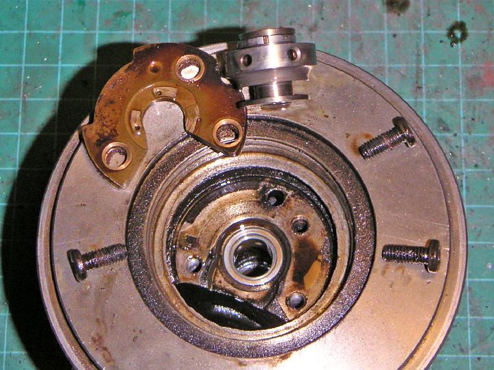 |
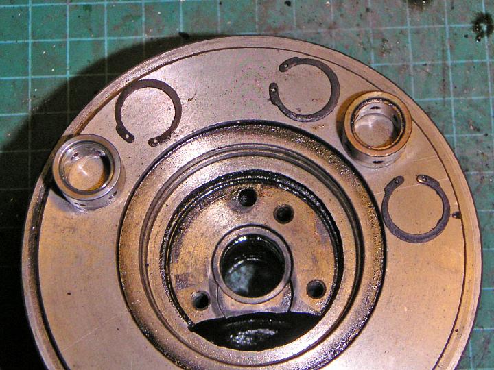
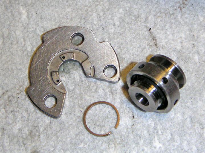
| 09.10.2005: Thrust bearing |
|
The thrust bearing is held by three Torx T15 screws. The thrust collar is
the part mainly responsible for shaft play.
|
 |
| 09.10.2005: Snap ring |
|
The journal bearings are held in place by small snap rings. You can remove
them with tiny needle-nose pliers or just an awl.
|
 |
| 09.10.2005: Journal bearings |
|
The intake side journal bearing has only one snap ring inside the turbo
(the outer side is propped by the thrust bearing), while the exhaust side
bearing has two snap rings.
|
 |
| 09.10.2005: Cleaning |
|
Time to clean all the grime and oil from the turbo. Check for sludge in the
oil passages. Keep all parts free from contaminants from now on.
|
 |
| 09.10.2005: Wheels |
|
Clean the wheels. Make sure you did not wipe your position marks if
you used a marker or paint. Remove the old seal ring from the turbine.
|
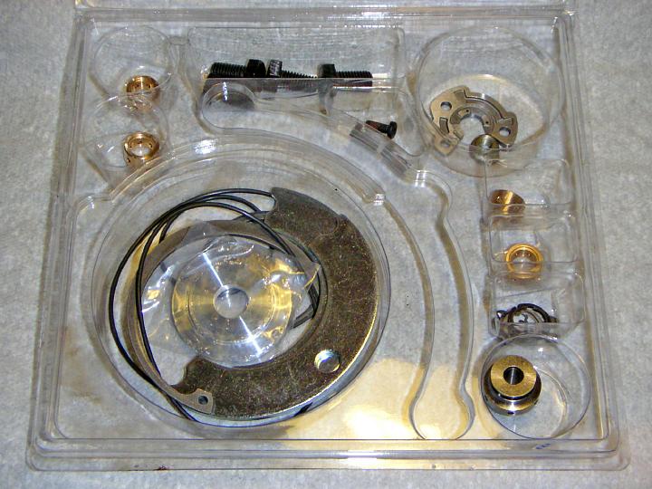 |
| 09.10.2005: The kit |
|
A typical T25 service kit from eBay
would contain a full set of new bearings, seals, snap rings and fasteners.
|
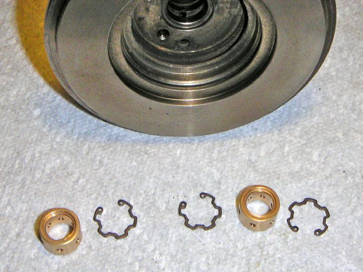 |
| 09.10.2005: Journal bearings |
|
Prepare journal bearings and snap rings. Some kits come with bearings in
two sizes to suit different trims of the turbo, so pick the right size.
|
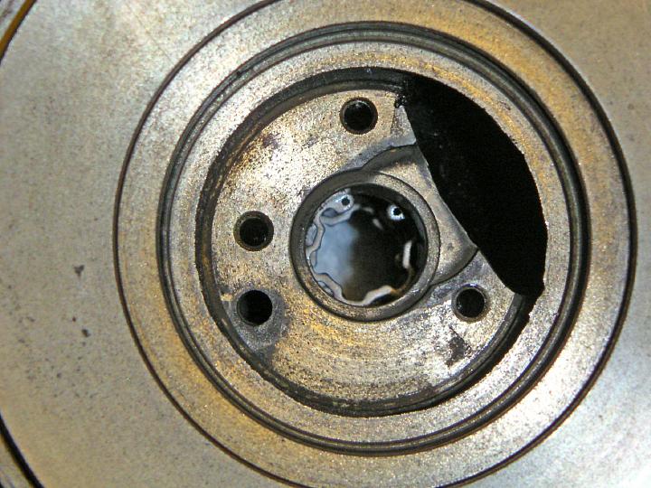 |
| 09.10.2005: Snap rings |
|
Install the inner snap rings on both sides of the central oil passage.
Make sure they fully fit into their grooves.
|
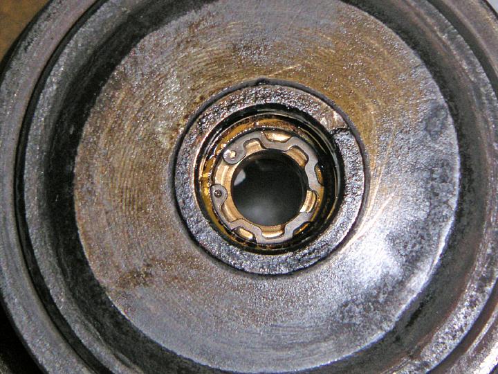 |
| 09.10.2005: Turbine side |
|
Dip one of the journal bearings in engine oil and insert it on the
exhaust side of the turbo. Fit the outer snap ring.
|
 |
| 09.10.2005: Compressor side |
|
Turn the turbo around, dip the second journal bearing in oil and slide
it in place.
|
 |
| 09.10.2005: Thrust bearing |
|
Fit the seal ring on the thrust collar, dip the parts in oil and screw
on the thrust bearing.
|
 |
| 09.10.2005: Sealplate |
|
Install a fresh rubber ring under the sealplate, press the sealplate in
and secure it with a snap ring.
|
 |
| 09.10.2005: Turbine |
|
Prepare the seals that go on the turbine end of the shaft.
|
 |
| 09.10.2005: Turbine seals |
|
The middle retaining ring was completely missing on both turbos. Its
groove was filled flush with cooked oil, so I had to dig through it.
The installation of the shaft is a bit awkward since you have the back
cover plate blocking the view, but sooner or later it snaps in. Just don't
force it too much.
|
 |
| 09.10.2005: Compressor wheel |
|
Slide the compressor wheel on and line up the marks carefully to restore
the balance. Put on the nut. The torque varies from 20 to 40 in-lbs in
various sources, plus extra 90-120°. Ideally, you need a small
12-pt socket for the nut, I just clamped it between two wooden blocks and
used a torque wrench on the turbine end.
|
 |
| 09.10.2005: Compressor housing |
|
Fit new rubber ring, put the housing on, and secure that huge snap ring.
Check the orientation: if the outlet of the housing points down, the part
number plate on the cartridge body (or the stud that's left of it) should
point up.
|
 |
| 09.10.2005: Exhaust housing |
|
Fit the exhaust housing, new brackets and tighten the bolts. As usual, make
sure the turbine spins free.
|
 |
| 09.10.2005: Wastegate actuator |
|
The wastegate actuator has been
rebuilt
and prepared earler, with an upgraded spring from
Nordic.
|
 |
| 09.10.2005: Finished |
|
Bolt the actuator to the housing and screw on the arm so it slides
onto the wastegate arm in the closed position. Shorten the rod an extra 2-3
turns to obtain a pre-load of 2-3 mm, and tighten the lock nut.
|


