 |
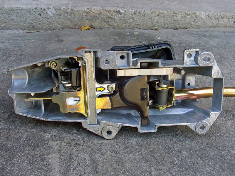
| 17.06.2007: Reverse lock |
|
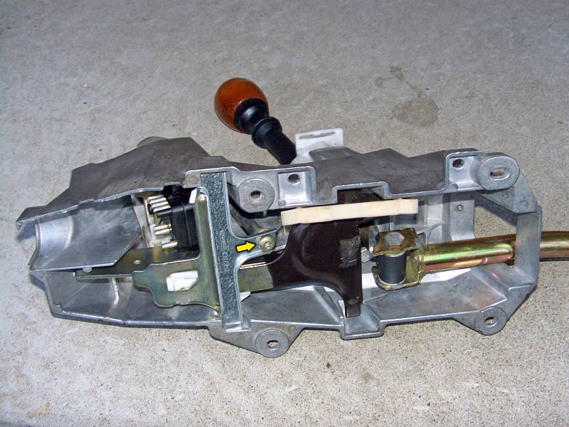
Undo the screw holding the reverse lock plate (Torx T30). Detach the
plastic lever leading to the ignition lock from its ball socket and
remove the plate.
|
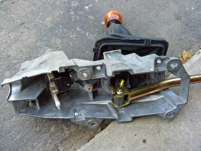 |
| 17.06.2007: Linkage rod |
|
Undo the bolt holding the long linkage rod to the bottom of the shifter.
Older cars use a bolt with a Torx T30 head, newer bolts come with a 13 mm
hex head.
|
 |
| 17.06.2007: Spring |
|
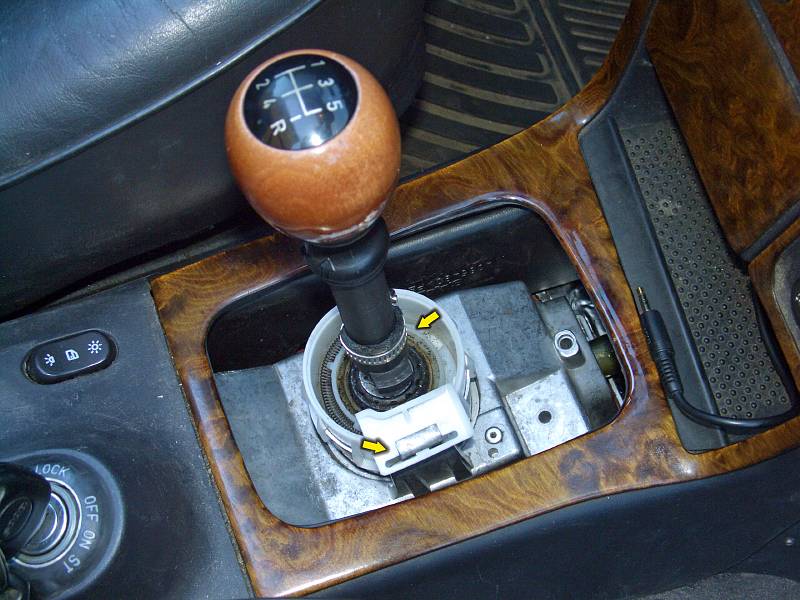
Use needle nose pliers to unhook the spring from the plastic housing.
|
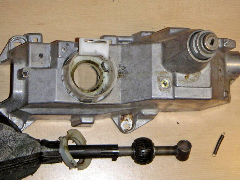 |
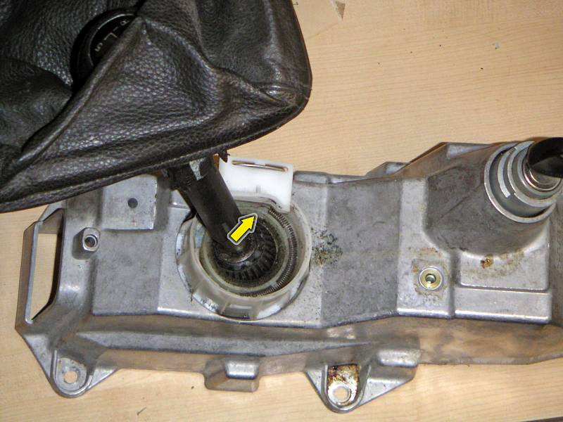
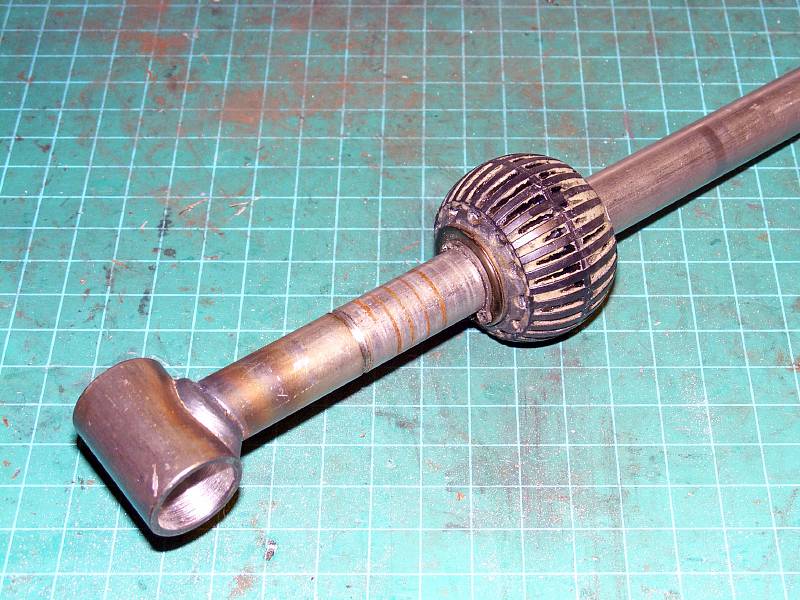
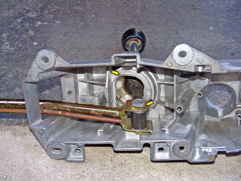
| 17.06.2007: Stick |
|
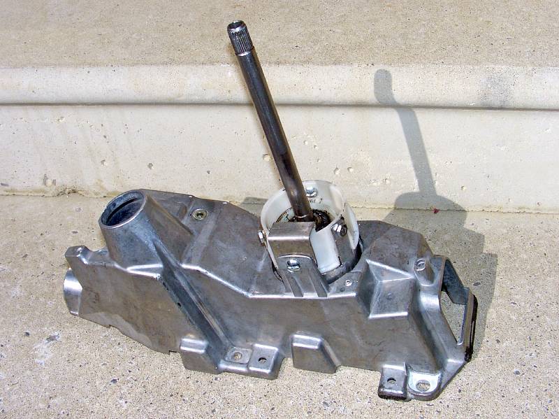
Turn the plastic retainer that holds the ball and lift the shifter rod out.
|
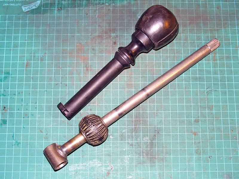 |
| 17.06.2007: Knob |
|
Pulling the knob off the rod takes considerable force, be careful not to
break it. In most cases you won't even need to do that. Just cut 20-30 mm
off the bottom of the plastic sleeve.
|
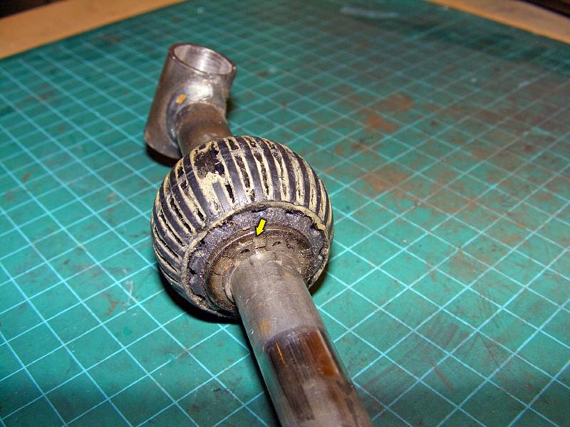 |
| 17.06.2007: Ball |
|
The ball is secured with two snap rings. Unseat the snap rings from
their grooves, and you can push the ball back and forth along the rod.
|
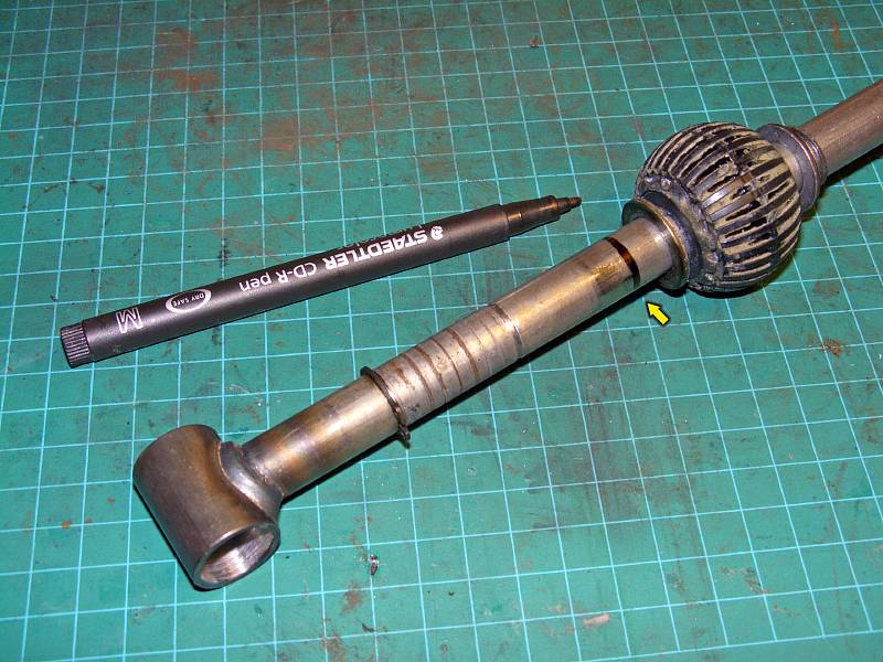 |
| 17.06.2007: Relocating |
|
One option is to cut a new groove 30 mm away from the old upper groove.
This is the limit the shifter can be adjusted to. 30 mm will already be
pushing the limits of the shifter housing, and the shifter will be very
heavy.
|
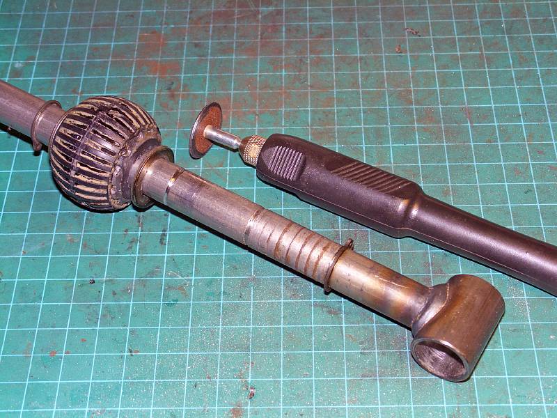 |
| 17.06.2007: Cutting |
|
The better option would be to cut TWO new grooves about 20-25 mm up from the
old ones. This way you will have more clearance inside the housing,
and the shifter will feel a bit lighter. A rotary cutter does the job here.
|
 |
| 17.06.2007: New position |
|
Move the ball into the new position and secure the snap rings in their
grooves.
|
 |
| 17.06.2007: MP shifter |
|
A third option would be to use an adjustable shifter rod from MP Performance
if you still can source one - they don't make those anymore.
|
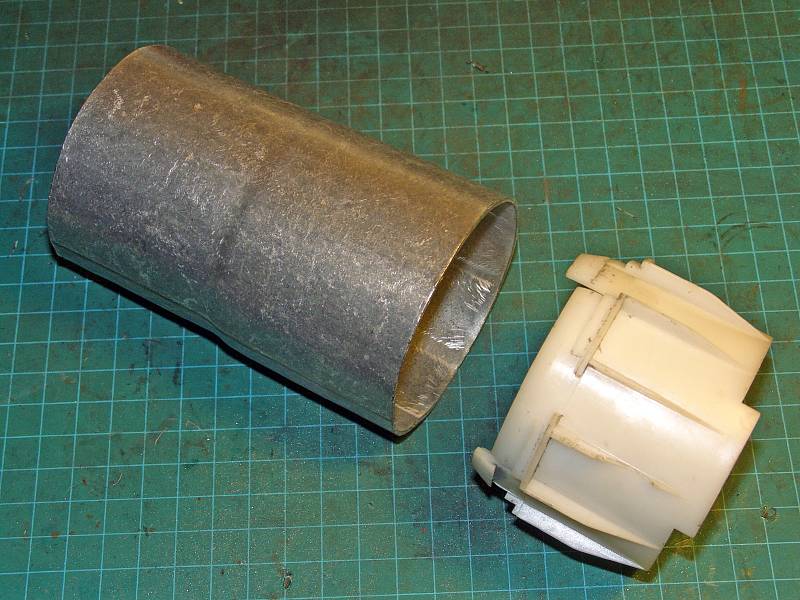 |
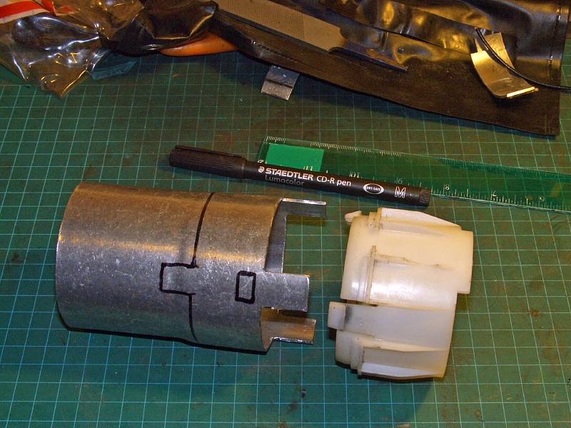
| 17.06.2007: Pipe |
|
This 2.75" O.D. piece of pipe will serve to raise the fulcrum point.
|
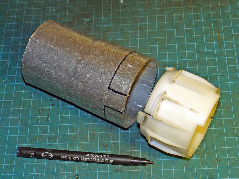 |
| 17.06.2007: Marking up |
|
Mark the pipe to make the flaps that will extend above the plastic latches.
|
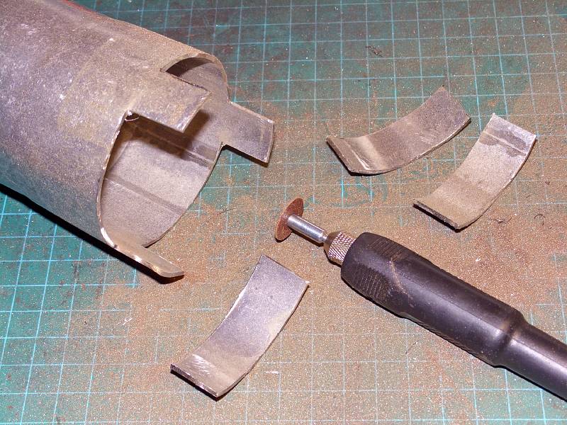 |
| 17.06.2007: First cut |
|
Cut away excess metal. Try to be precise, the flaps must closely match
the width of the grooves they go into for a tighter fit.
|
 |
| 17.06.2007: Cut off line |
|
Mark the bottom flaps and rectangular slots for plastic latches. Take
precise measurements, so there won't be any slack with the latches
locked. The height of the extender should be equal to the distance you
moved the ball, i.e. 20-25 mm.
|
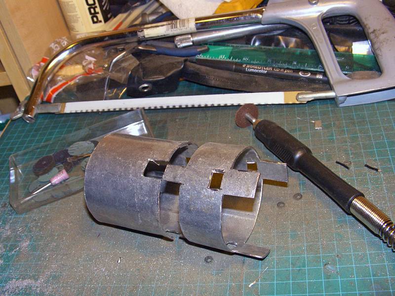 |
| 17.06.2007: Cutting finished |
|
Cutting a fancy profile in a thick mild steel pipe is not a lot of fun.
I used up a dozen cut-off wheels and switched to the old good hack saw for
the final horizontal cut.
|
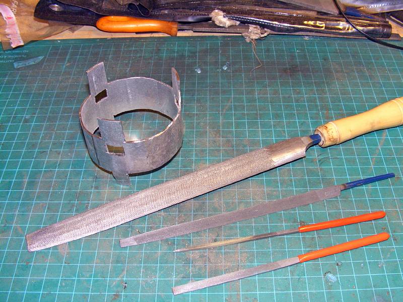 |
| 17.06.2007: Deburring |
|
Take your time cleaning and deburring the extender. Check the fit with the
plastic ball socket and adjust if needed.
|
 |
| 17.06.2007: Ready to fit |
|
The lower flaps should be cut a bit deeper into the body of the extender
so they can be bent inward in the middle.
|
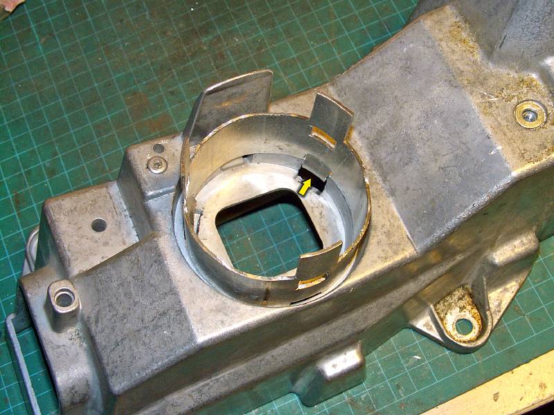 |
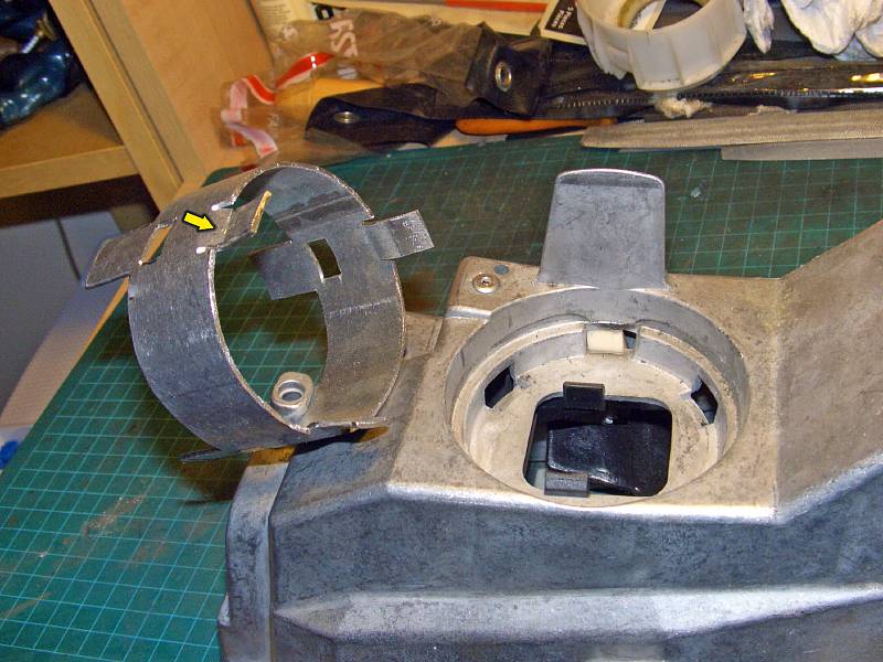
| 17.06.2007: In position |
|
Position the extender in the shifter housing so the lower flaps fit the holes
previously occupied by plastic latches.
|
 |
| 17.06.2007: Flaps bent |
|
Bend the flaps outward to secure the extender in place. If you need extra
strength, you can make the flaps longer, drill through and screw them onto
the housing, but I've found they hold pretty well when bent like this.
|
 |
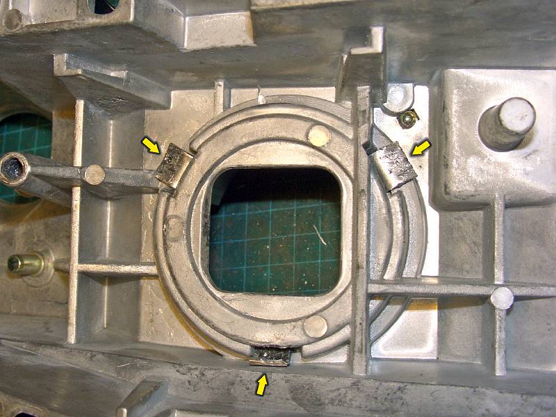
| 01.07.2007: Screws |
|
Here's an alternative version where the extender is secured by four screws.
The opening in the shifter housing is trimmed to allow for extra movement.
|
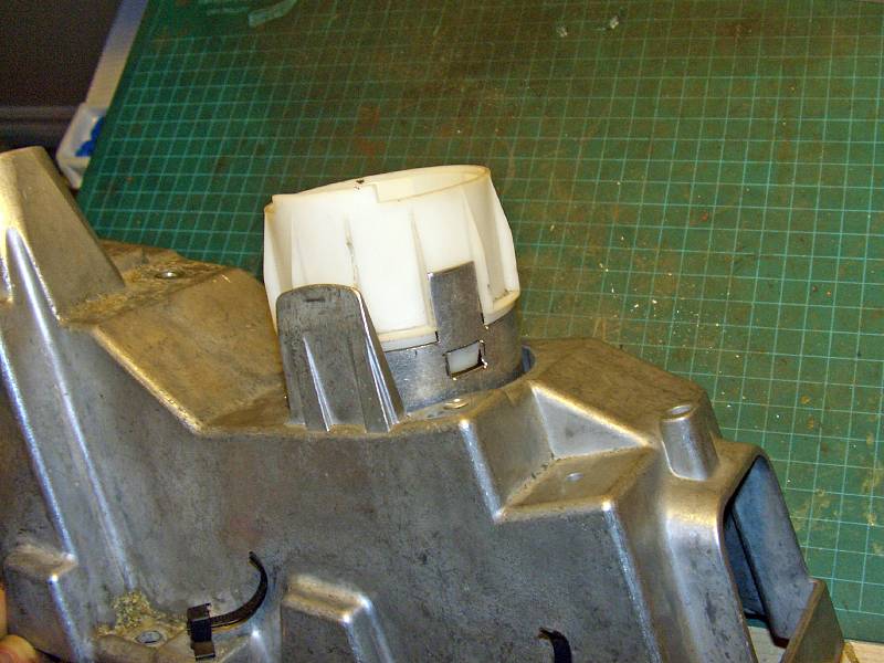 |
| 17.06.2007: Plastic socket |
|
Slide the plastic ball socket in until the latches click. It should fit
tightly if you followed the measurements. Again, you can drill through the
flaps and secure them to the plastic housing with small screws.
|
 |
| 17.06.2007: Trimming |
|
If you went to the full 30 mm on the shifter rod, you might have to not
only trim the housing, but also grind the lower bolt so it's flush
with the surface of the nut on the linkage rod.
|
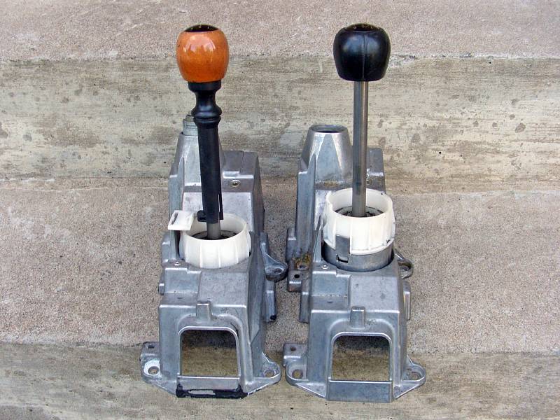 |
| 17.06.2007: Old vs new |
|
I had a luxury of having an extra housing to experiment with. Here's the
original housing next to the modified version.
|
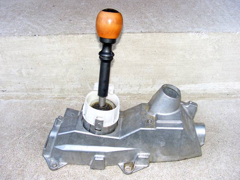 |
| 17.06.2007: New handle |
|
My wooden knob is transferred to the new housing. The plastic sleeve is cut
about 25 mm shorter at the bottom.
|
 |
| 17.06.2007: Ignition lock |
|
The ignition lock is installed into the modified housing.
|
 |
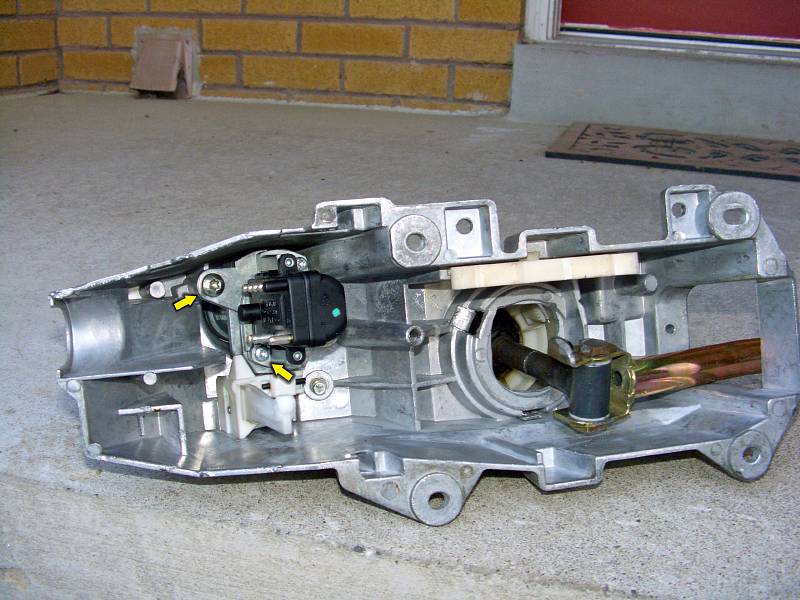
| 17.06.2007: Reverse lock |
|
Next, the reverse locking plate goes in. Check if it works correctly
before installing the shifter back into the car.
|
 |
| 17.06.2007: 5th gear catch |
|
The bottom part of the plastic stalk sleeve can be re-attached using glue or
a small hose clamp. And the flimsy 5th gear catch needs to be reinforced so
you don't bend it every time you shift into 5th.
|
 |
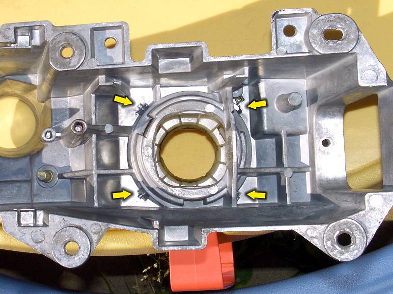
| 01.07.2007: New version |
|
An updated version of the modified housing with a metal 5th gear catch.
The plastic ball socket is bolted to the extender for extra strength.
|


