 |
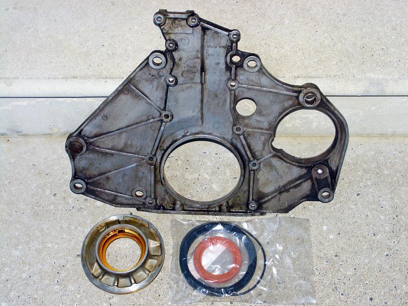
| 02.07.2006: Crankshaft seals |
|
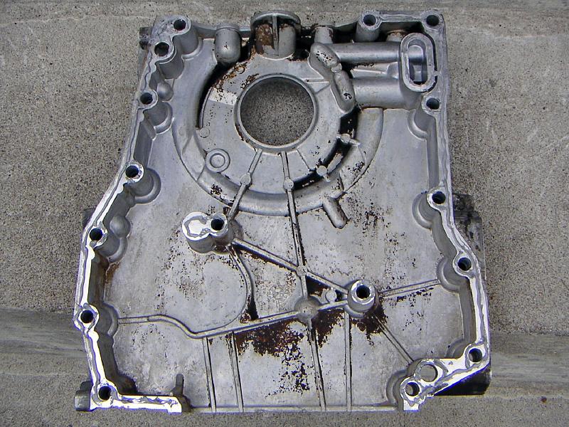
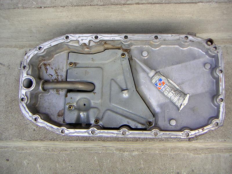
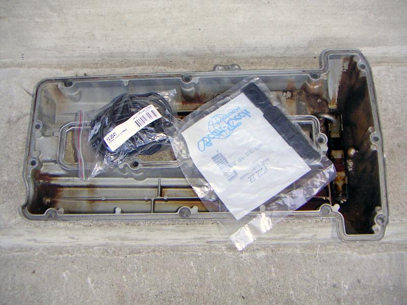
Before starting the assembly, make sure you have all spare parts needed.
This picture shows the endplate and oil pump cover with a pack of fresh
seals for them.
|
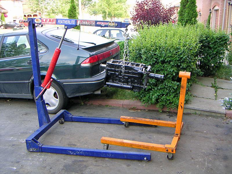 |
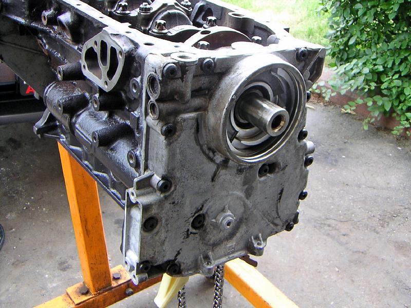
| 02.07.2006: Suspended |
|
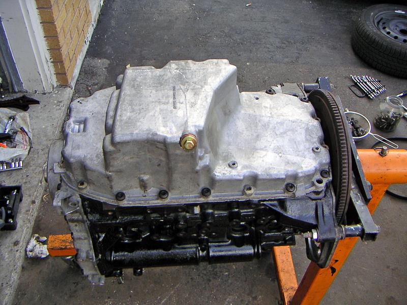
If you are using an engine stand that bolts on to the gearbox mounting
points, you won't be able to attach the endplate. In this case, suspending
the engine on a hoist does the job.
|
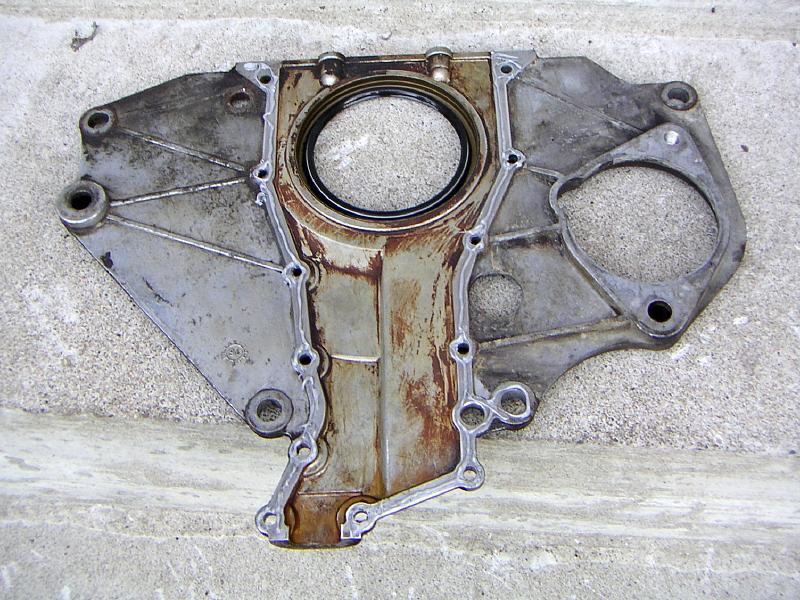 |
| 02.07.2006: Endplate |
|
Clean the endplate, tap the new seal in and apply a thin bead of sealant
to the mating surface.
|
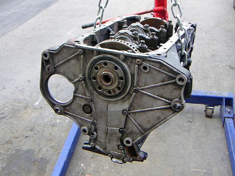 |
| 02.07.2006: Endplate attached |
|
Fit the plate and tighten the screws (Torx T30 socket). Wipe the excess
sealant.
|
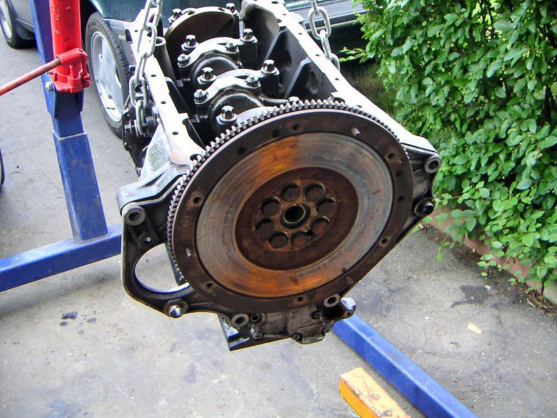 |
| 02.07.2006: Flywheel |
|
Attach the flywheel, apply some threadlock to the bolts and tighten them
to 59 ft-lbs (19 mm socket). Use a flywheel stop or have a helper
hold the crank pulley nut on the other end to prevent the crankshaft
from spinning.
|
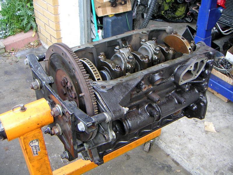 |
| 02.07.2006: Back on the stand |
|
Put the engine back on the stand. It might need some extra washers to clear
the flywheel. Turn the flywheel to match the "0" mark on the endplate.
|
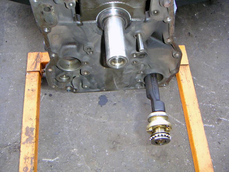 |
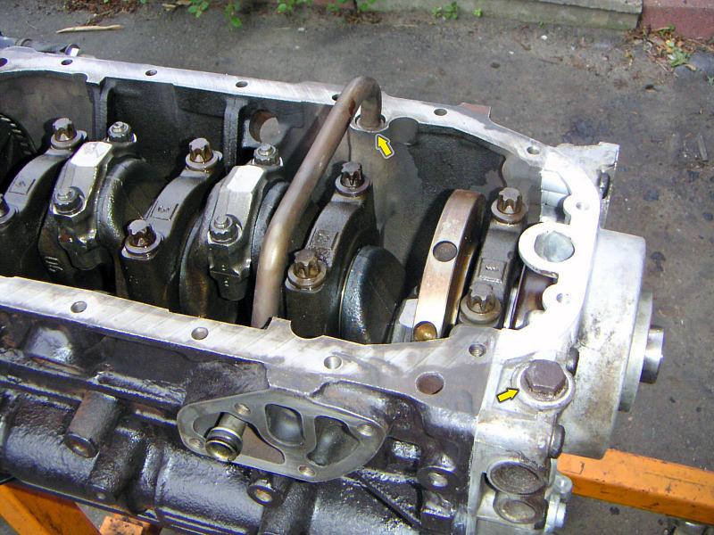
| 02.07.2006: Balance shaft |
|
Lubricate the balance shafts and carefully insert them trying not to
scratch the bearing surfaces inside the block.
|
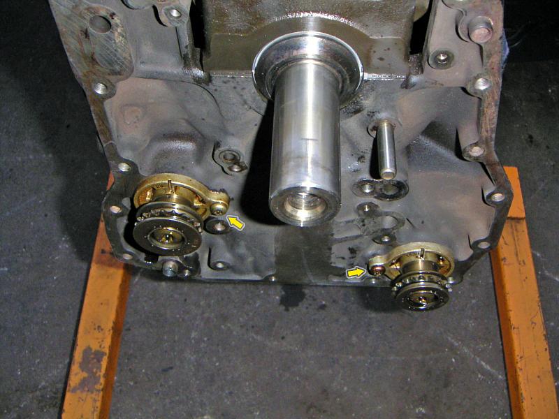 |
| 02.07.2006: Shafts in |
|
The shafts are the same, but the sprockets are not. The intake shaft has a
smaller sprocket marked "INL", while the exhaust side is marked "EXH".
Tighten the screws (Torx T30).
|
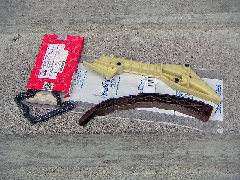 |
| 03.07.2006: Chain and guides |
|
Prepare a new timing chain and plastic guides.
|
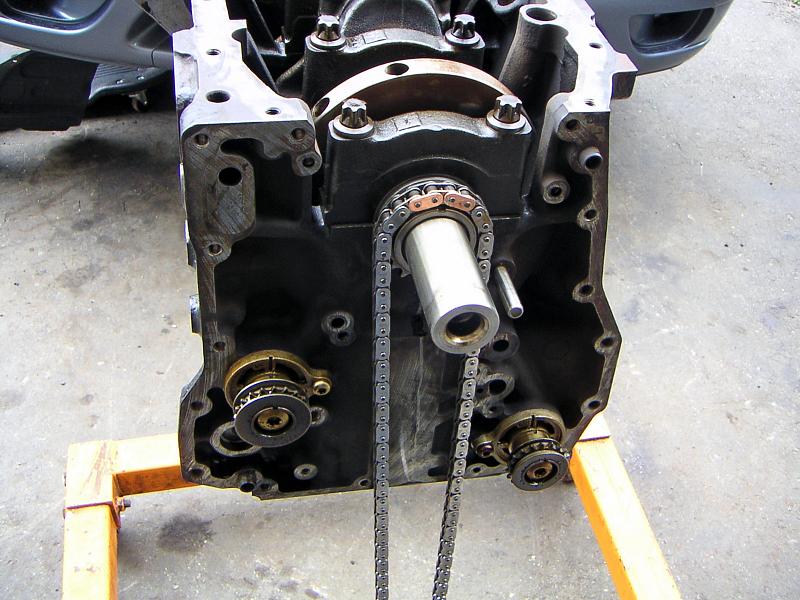 |
| 03.07.2006: Timing chain |
|
Fit the timing chain sprocket and hang the chain off it so the
colored link matches the notch on the sprocket (there are two other
colored links on the other end of the chain that will match the camshafts).
|
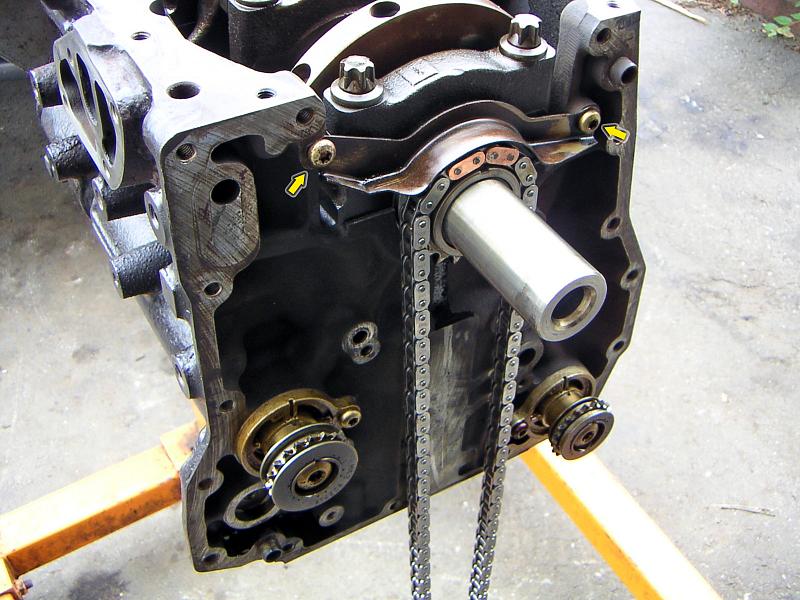 |
| 03.07.2006: Chain guard |
|
Attach the chain guard (two Torx T30 screws).
|
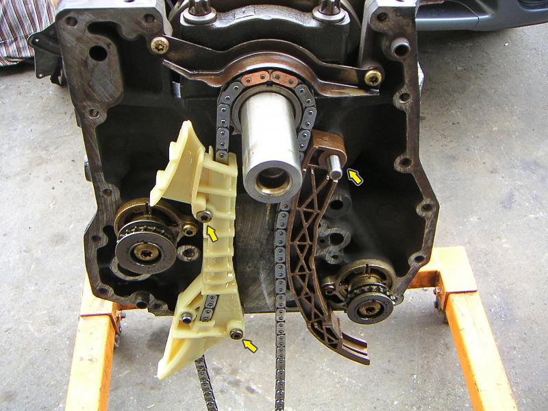 |
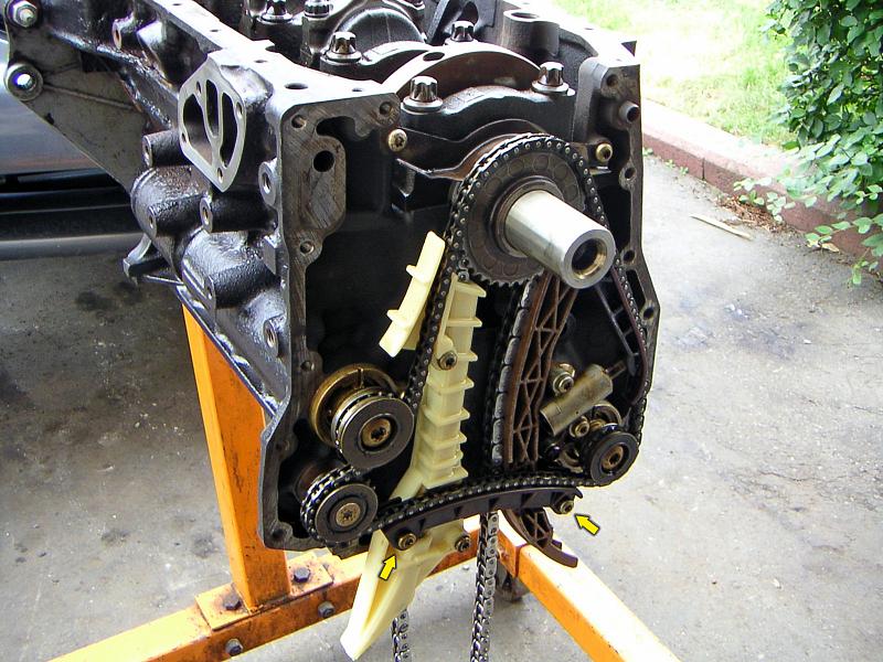
| 03.07.2006: Guides |
|
Fit the guides. The fixed guide is held by two long T30 screws, while
the swivel guide just sits on a big pin.
|
 |
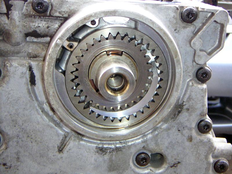
| 03.07.2006: Balance shaft |
|
Turn the balance shafts so the notch matches the mark on the housing.
|
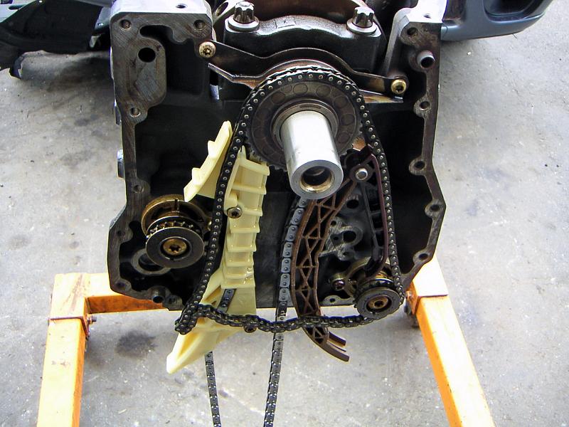 |
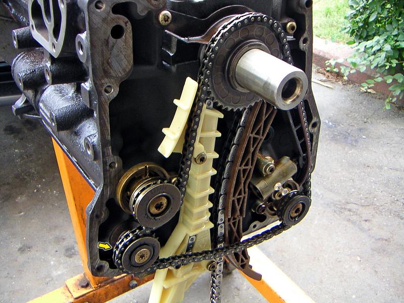
| 03.07.2006: Balance chain |
|
Fit the balance chain sprocket, the small swivel guide and the balance
shaft chain.
|
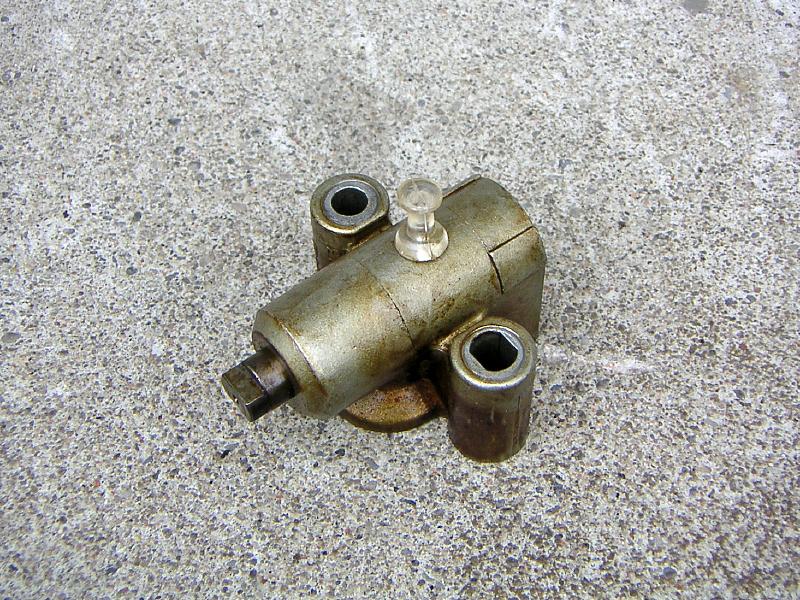 |
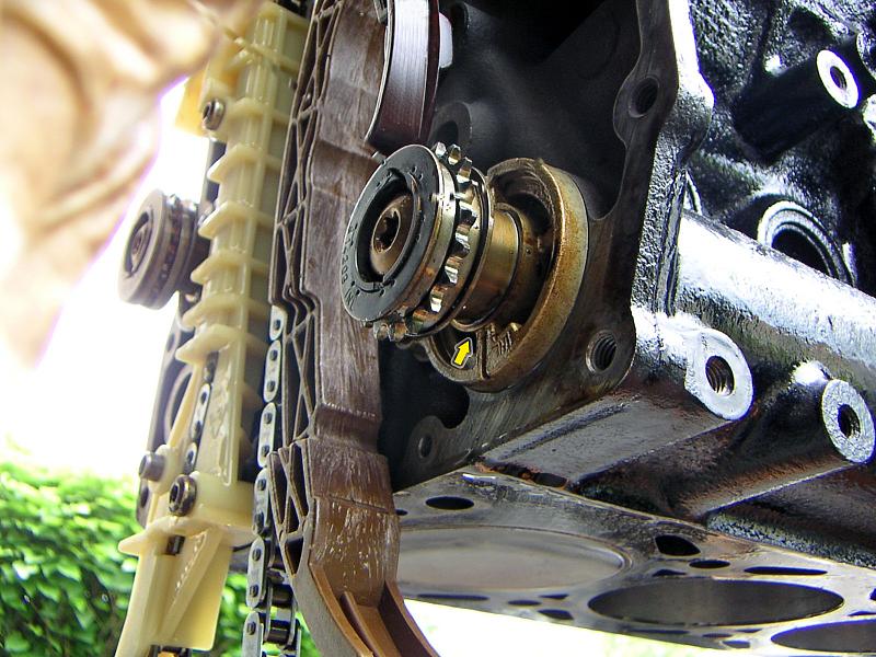
| 03.07.2006: Tensioner |
|
Push the piston on the balance chain tensioner in and lock it with a pin
or a paper clip.
|
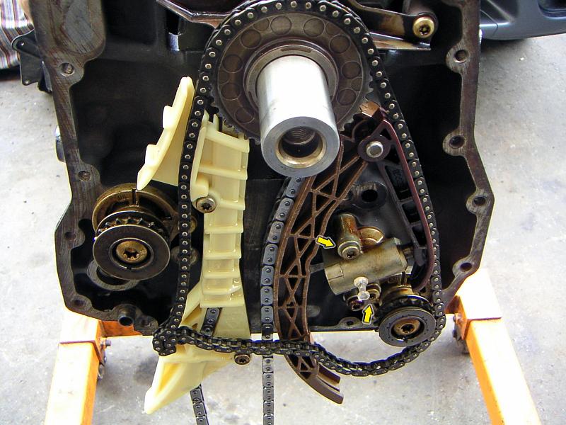 |
| 03.07.2006: Tensioner fitted |
|
Attach the tensioner and tighten the screws to 7.4 ft-lbs (the factory
manual makes a big deal about it).
|
 |
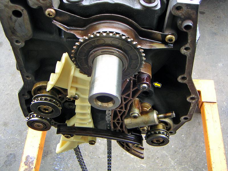
| 03.07.2006: Idle sprocket |
|
Fit the balance chain idler sprocket (Torx T40).
|
 |
| 03.07.2006: Upper guide |
|
Attach the upper balance chain guide with two more T30 screws (the engine
is upside down, so it's at the bottom) and release the tensioner. Turn the
crankshaft and check if the shaft notches are still in sync with a "0" mark on
the flywheel after a few revolutions.
|
 |
| 03.07.2006: No chain |
|
If you choose to build the engine without a balancing chain, you can leave
the shafts and sprockets in to preserve the proper oil flow. Just replace
the swivel guide with a spacer so it doesn't rattle inside the engine.
|
 |
| 03.07.2006: Timing cover |
|
Clean the mating surfaces of the timing cover and apply a bead of sealant.
|
 |
| 03.07.2006: Timing cover |
|
Fit the cover and tighten the bolts to 16 ft-lbs (Torx T40 socket).
|
 |
| 03.07.2006: Oil pump |
|
Lubricate and insert the oil pump gears making sure that the marking on the
oil pump ring gear is facing out and the pump gear with flange facing in.
|
 |
| 03.07.2006: Oil pump cover |
|
Tap a new seal into the oil pump cover, put the cover on and secure
it with a snap ring.
|
 |
| 03.07.2006: Oil tube |
|
Fit the oil feed tube and refresh the O-rings on it.
Screw in the reducer valve.
|
 |
| 03.07.2006: Oil pan |
|
Attach the pickup screen and the splash guard inside the oil pan,
apply a bead of sealant to the flange.
|
 |
| 03.07.2006: Pan fitted |
|
Tighten the oil pan screws to 16 ft-lbs (Torx T40). Fit a fresh drain plug
washer.
|
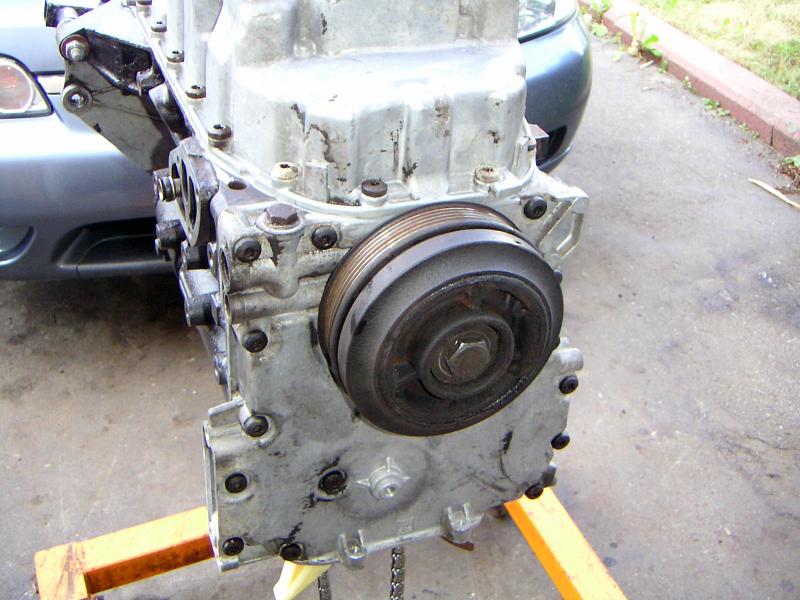 |
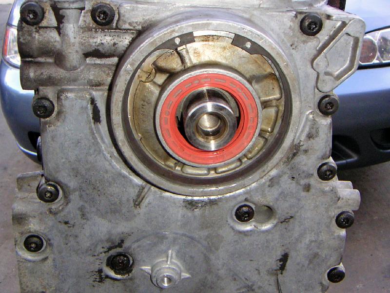
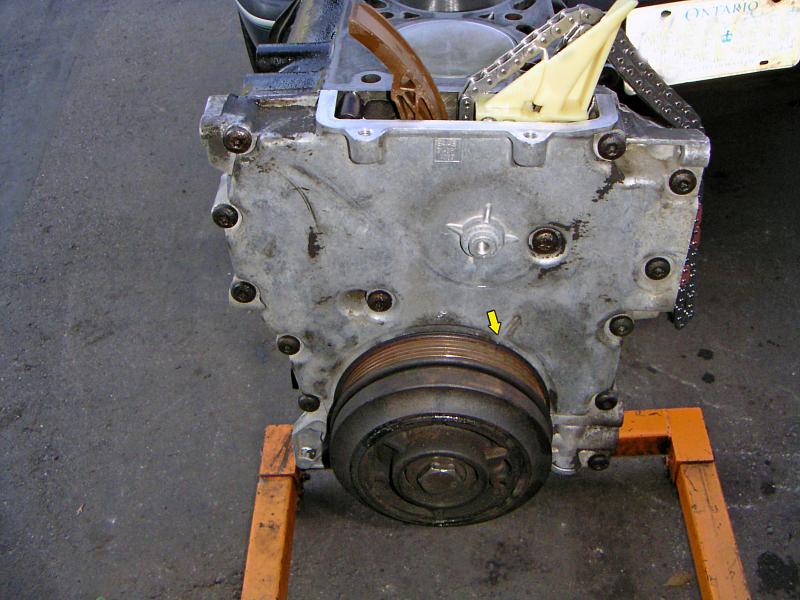
| 03.07.2006: Crankshaft pulley |
|
Slide the crankshaft pulley on (mind the oil seal in the oil pump cover)
and tighten the 27 mm bolt to 130 ft-lbs.
|
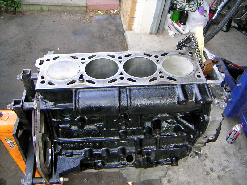 |
| 04.07.2006: Top of the block |
|
Turn the block upright and clean the upper surface.
|
 |
| 04.07.2006: TDC mark |
|
Turn the crankshaft pulley to match the TDC mark.
|
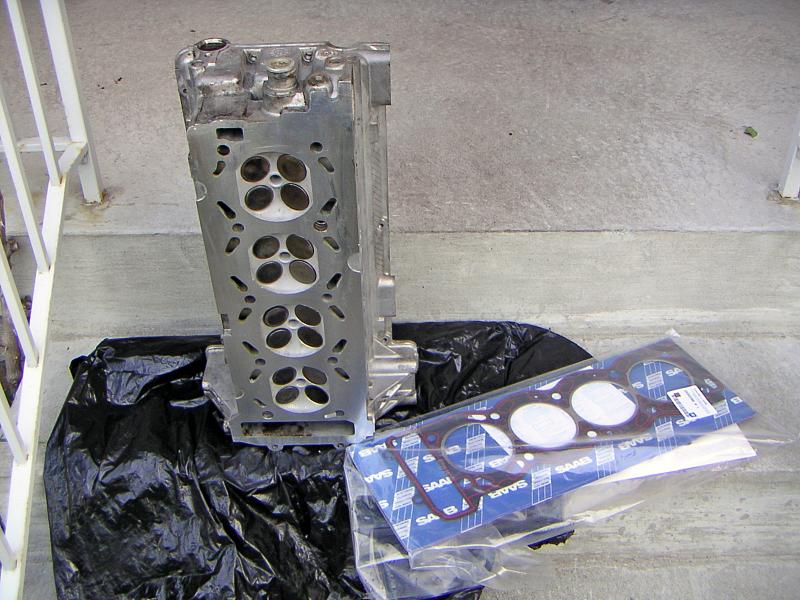 |
| 04.07.2006: Head and gasket |
|
Prepare the head with a fresh gasket. Clean the head flange thoroughly.
|
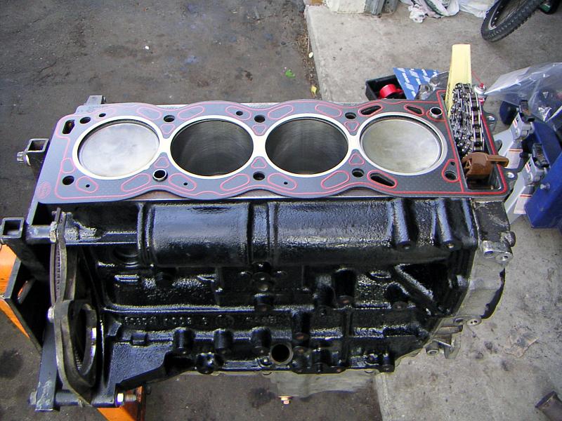 |
| 04.07.2006: Gasket |
|
Put the gasket on top of the block, make sure it clears the locating dowels.
|
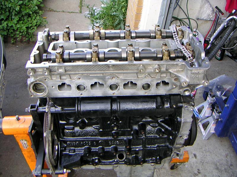 |
| 04.07.2006: Head |
|
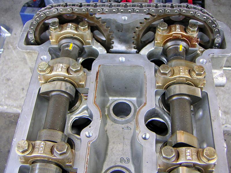
Set the camshafts to zero (see the markings on the #1 cap) and put the head
carefully on the block.
|
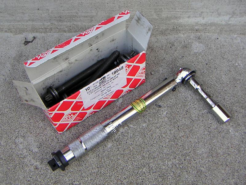 |
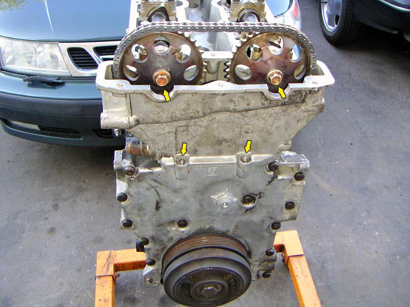
| 04.07.2006: Head bolts |
|
A new set of head bolts is needed to attach a head. The old bolts are
already stretched and won't provide a proper clamping force.
|
 |
| 04.07.2006: Head bolts |
|
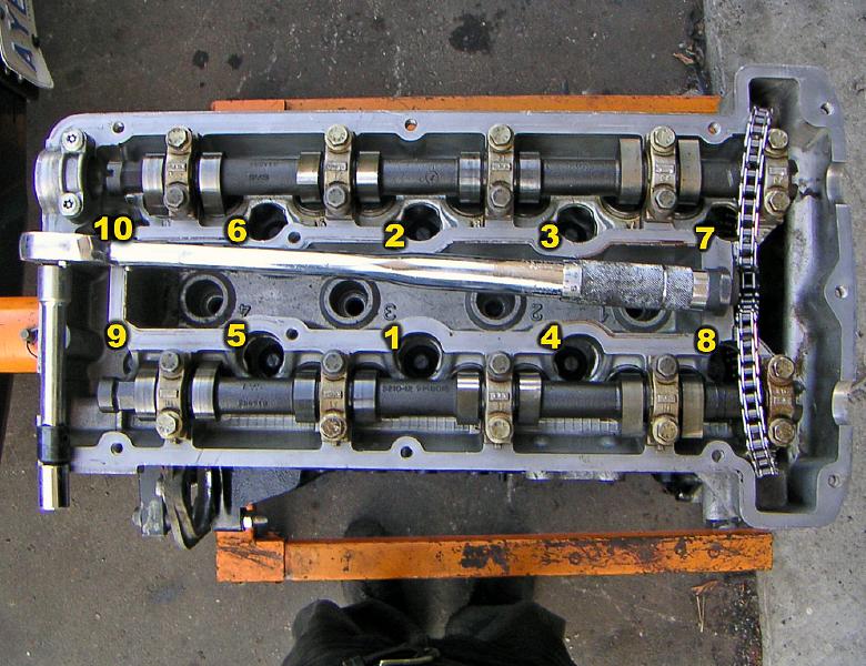
Tighten the bolts to 44 ft-lbs in the order shown. Then do a second pass
and tighten them to 59 ft-lbs. Grab a bigger wrench and do a third pass,
turning every bolt an extra 90°.
|
 |
| 04.07.2006: Camshafts |
|
Fit camshaft sprockets, starting with the intake side. Check that both
camshafts and the crankshaft remain at their "0" mark. Screw the sprocket
bolts in but not tighten them yet.
|
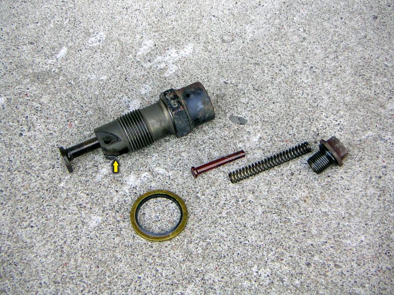 |
| 04.07.2006: Tensioner |
|
Take apart the timing chain tensioner and clean it. Press on the catch
and compress the piston completely.
|
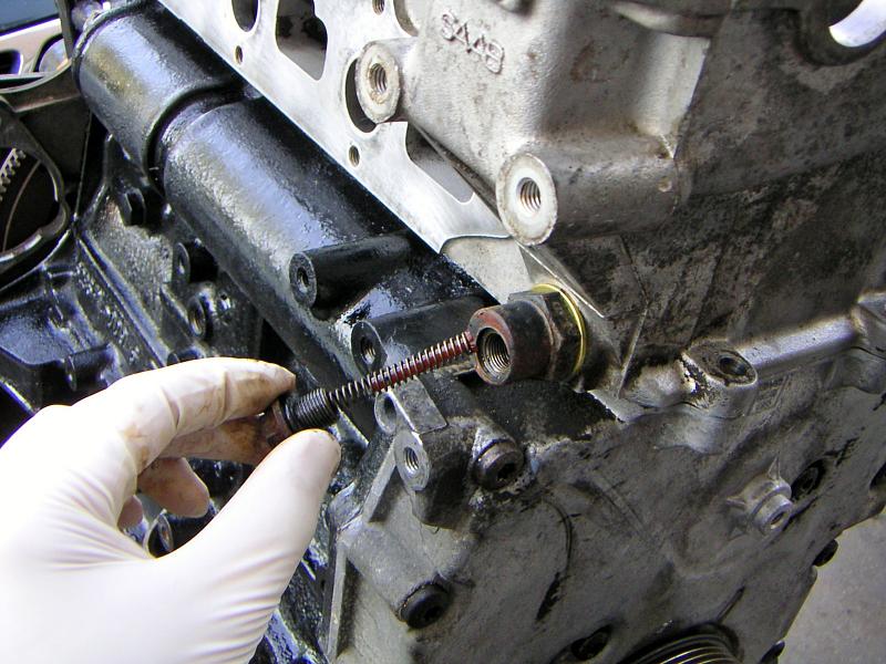 |
| 04.07.2006: Tensioner |
|
Install the tensioner with a new washer while keeping it in a compressed
state. Tighten to 47 ft-lbs (27 mm socket). Insert the spring and tighten
the plug to 16 ft-lbs.
|
 |
| 04.07.2006: Sprocket bolts |
|
Rotate the crankshaft clockwise and ensure that zero marks on the camshafts
and crank pulley are still in sync after a few revolutions. Tighten sprocket
bolts to 47 ft-lbs (14 mm socket), tighten the two upper timing cover bolts
to 16 ft-lbs (12 mm socket).
|
 |
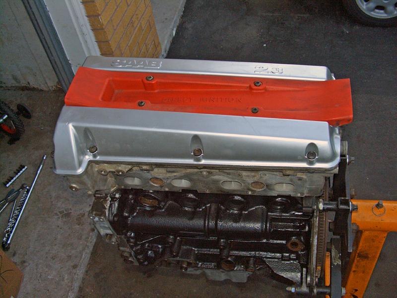
| 04.07.2006: Valve cover |
|
Clean the valve cover and renew the upper timing chain guide. Apply
some soap to the valve cover gasket so it sticks to the groove.
|
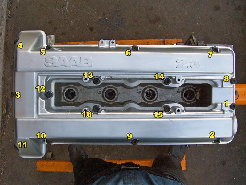 |
| 04.07.2006: Valve cover |
|
Fit the valve cover, make sure the gasket fills the half-moon openings
correctly and is not jammed anywhere. Tighten the bolts to 11 ft-lbs
in the order shown (Torx T40).
|
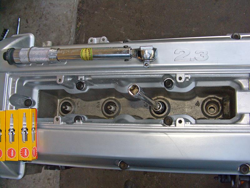 |
| 04.07.2006: Spark plugs |
|
Gap the spark plugs and tighten them to 20 ft-lbs. NGK BCPR7ES are the
plugs most recommended for this application.
|
 |
| 04.07.2006: DI cassette |
|
Install the ignition module and tighten the screws to 8 ft-lbs.
Congratulations, you've built yourself an engine!
|


