 |
| 21.06.2006: Cleaning |
|
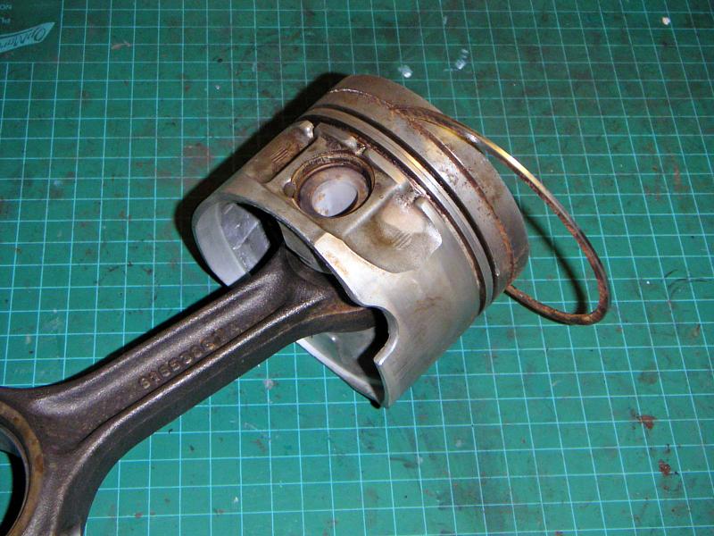
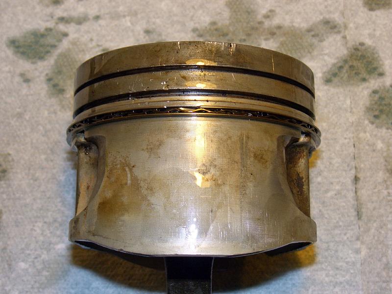
Before installing new piston rings, clean the pistons and scrape all
the ring grooves with an old ring to remove all dirt and reposits.
|
 |
| 21.06.2006: Rings |
|
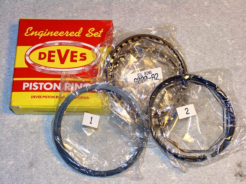
Aftermarket rings often come as a complete set, bagged and labelled for an
easy installation. Saab OEM rings would come as a "per piston" set.
|
 |
| 21.06.2006: Testing |
|
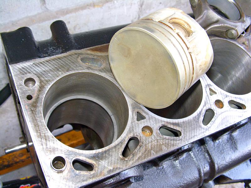
Oil the cylinder bores slightly and push the rings in with a piston top
one by one. Check the fit and measure the gap between the ring ends.
The factory specifies a 0.30-0.50 mm gap for the first compression ring
and a 0.16-0.65 mm for the second. If the rings were ordered correctly for
your application (e.g. standard size), you should not have to adjust them.
|
 |
| 21.06.2006: Rings ready |
|
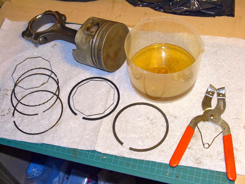
The first compression ring is a solid metal ring. The second is a scraper
type and might come with an expander ring (Saab OEM kits don't have
expander rings). The third ring is a multi-piece oil scraper, which has
two thin rails with a spacer between them, as well as an optional expander.
Have some oil ready to lubricate the rings before installation.
|
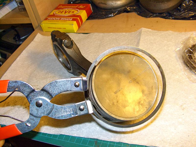 |
| 21.06.2006: Ring tool |
|
Although it's possible to install compression rings with your bare hands, it's much
easier with a ring expander. Use some old rings to practice. The #2s
seem to be more fragile, I broke a couple checking how far they would stretch ;)
|
 |
| 21.06.2006: Expander A |
|
The key point in installing piston rings is to fit them so the gaps of the
neighbor rings are as far from each other as possible. Start with the oil
scraper ring. Turn the piston so you're looking at the connecting rod pin,
and fit the expander ring (if you have it).
|
 |
| 21.06.2006: Rail B |
|
Turn the piston 90° and fit the lower scraper rail.
|
 |
| 21.06.2006: Spacer C |
|
Turn the piston another 90° and fit the spacer so its gap is
on the opposite side from the expander ring.
|
 |
| 21.06.2006: Rail D |
|
Finally, turn the piston yet another 90° and fit the upper scraper
rail.
|
 |
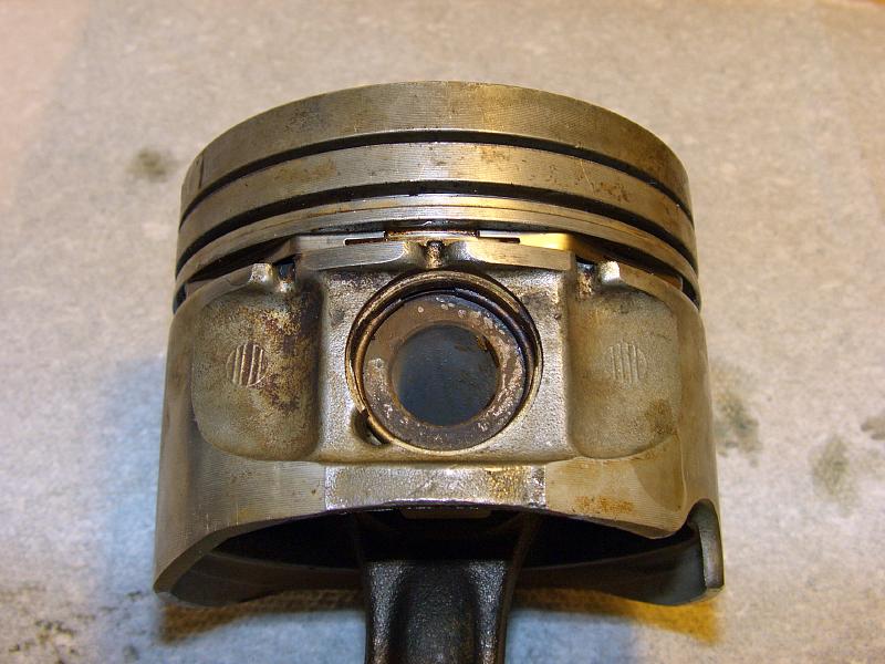
| 21.06.2006: Ring 2 Expander |
|
Go back to the wrist pin and fit the expander ring for the compression
ring #2 (if you have it).
|
 |
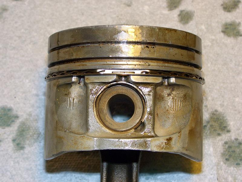
| 21.06.2006: Compression Ring 2 |
|
Turn the piston 180° and fit the lower compression ring. The ridge
on the ring should look down (the ring will likely have "top/bottom"
markings on it).
|
 |
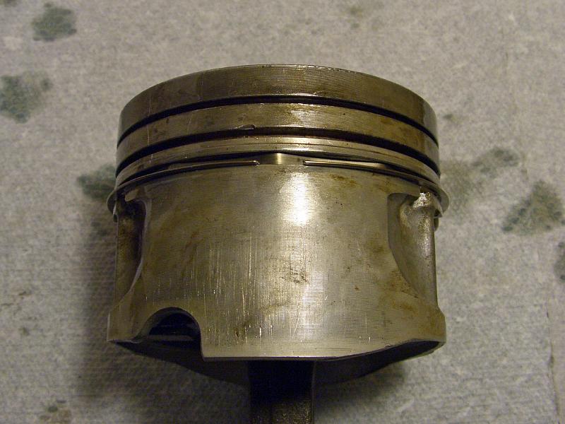
| 21.06.2006: Compression Ring 1 |
|
Fit the remaining top compression ring so the gap on it is on the opposite
side from the compression ring #2.
|
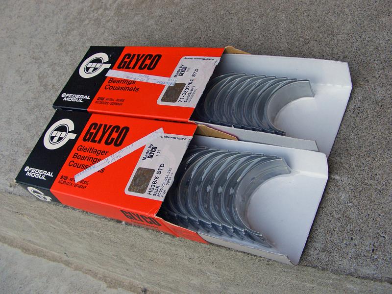 |
| 21.06.2006: Crankshaft bearings |
|
Crankshaft bearings come as thin semi-round metal shells with special
coating on them. Be sure to verify the label on the box before opening
as no supplier will take them back if you remove the protective film.
|
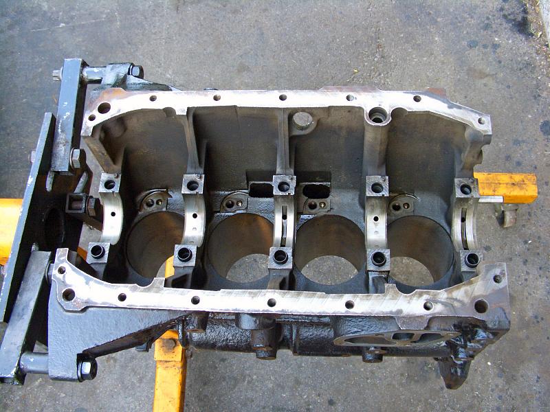 |
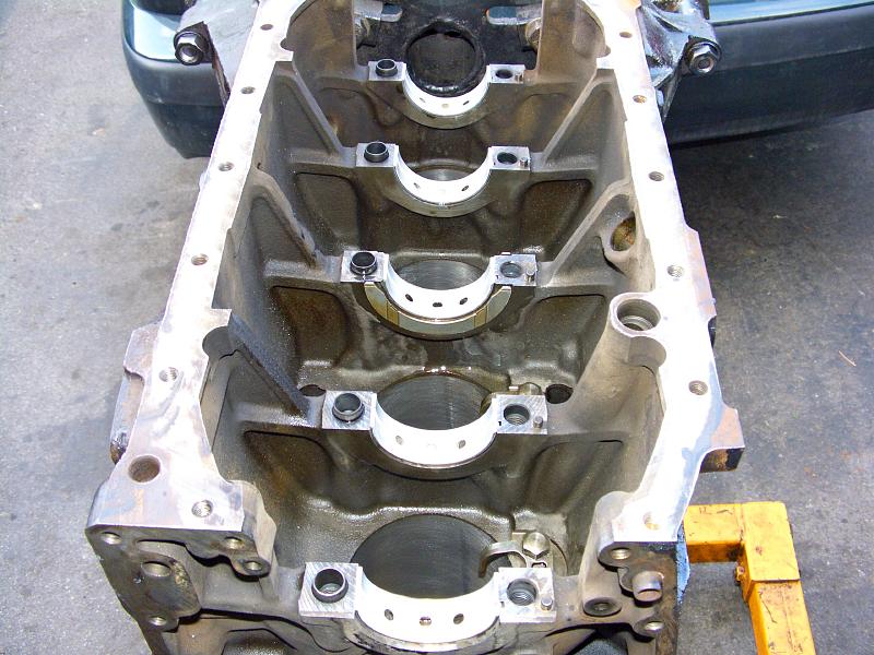
| 21.06.2006: Engine block |
|
Secure the engine block on the stand and throroughly clean the mating
surfaces.
|
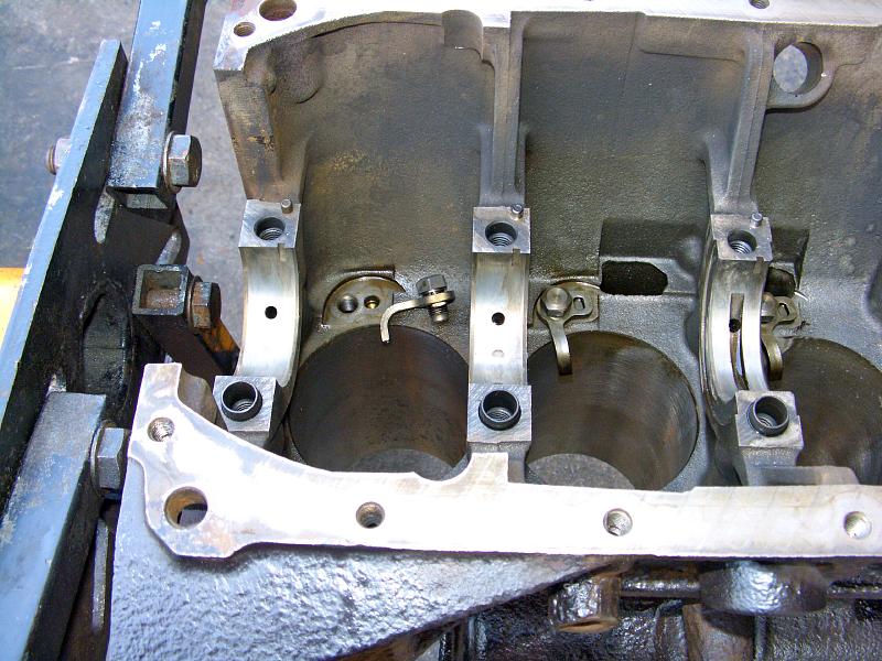 |
| 21.06.2006: Oil jets |
|
Attach the piston cooling oil jets (14 mm socket), ensuring their
correct orientation.
|
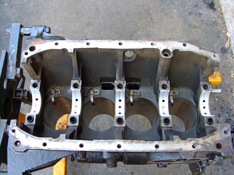 |
| 21.06.2006: Main bearings |
|
Carefully place five main bearing shells in their sockets, matching
the notch on one side. Avoid touching their surface with anything,
including your bare hands, as it would introduce dirt.
|
 |
| 21.06.2006: Thrust washers |
|
Install the thrust washers on both sides of the #3 bearing. The side
where the part number is embossed should face the bearing.
|
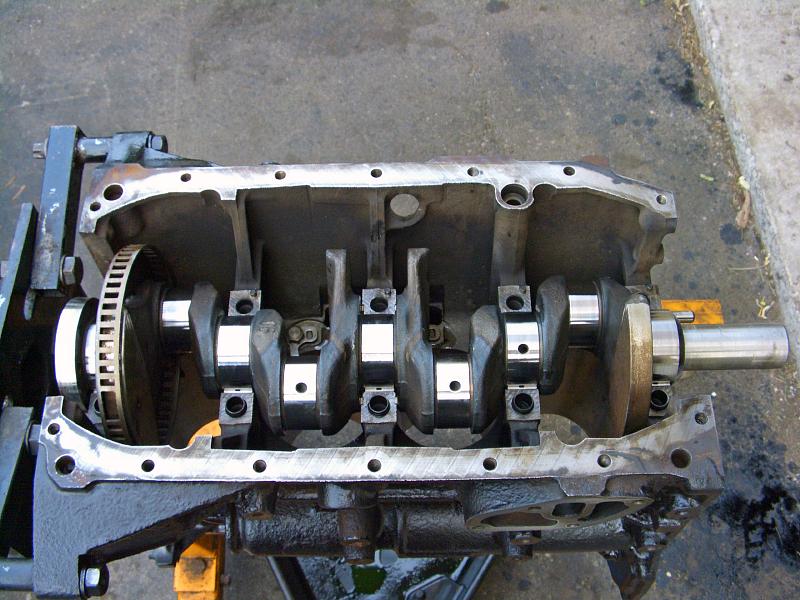 |
| 21.06.2006: Crankshaft |
|
Lubricate the bearings and place the crankshaft in position. Mind the
thrust washers as they like to drop on the floor at the first touch of
the crankshaft.
|
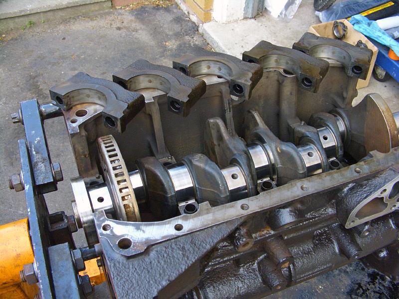 |
| 21.06.2006: Main caps |
|
Clean and prepare the main bearing caps. They are numbered 1 to 5,
starting from the timing cover.
|
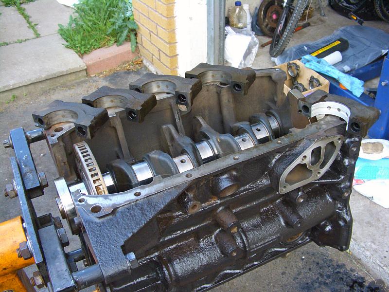 |
| 21.06.2006: Main bearing tops |
|
Place the remaining main bearings into their caps, lubricate them and
install the caps (they only fit one way).
|
 |
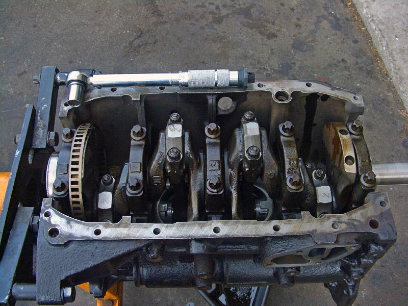
| 21.06.2006: Bolts |
|
Tighten the bolts to 81 ft-lbs (Torx E16 socket).
|
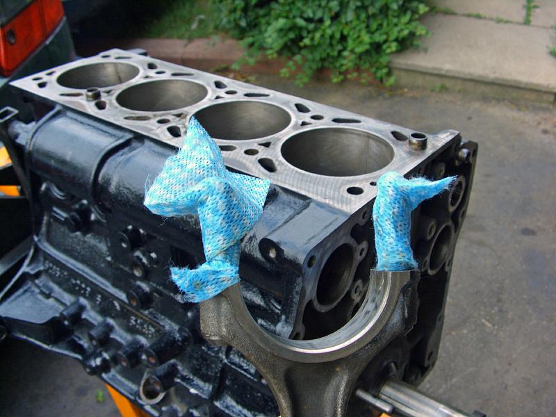 |
| 21.06.2006: Connecting rod |
|
On to the piston installation. Wrap the studs on the connecting rods
to avoid scratching the crankshaft while the piston is being inserted.
|
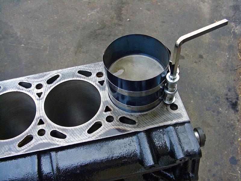 |
| 21.06.2006: Piston ring compressor |
|
Put the piston half-way into the cylinder and compress the rings with
a special tool.
|
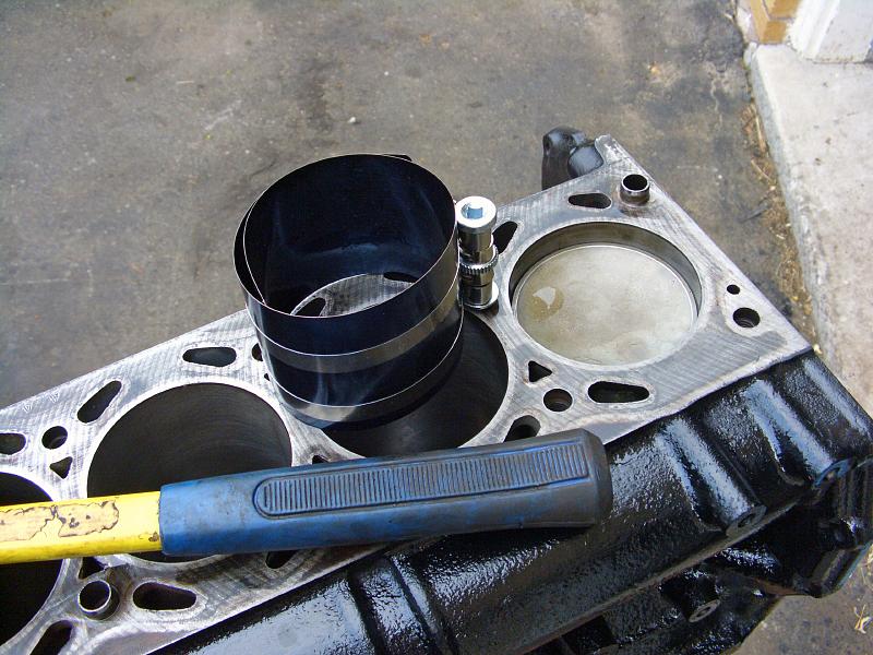 |
| 21.06.2006: Piston in |
|
Tap the piston gently with a rubber hammer handle until it fully enters
the cylinder.
|
 |
| 21.06.2006: Rod cap |
|
Place the bearing shell into the rod, oil it and tap the piston further
until the rod is in full contact with the crankshaft. Place the other
shell into the cap and put the cap on.
|
 |
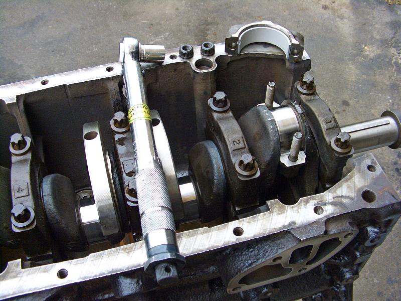
| 21.06.2006: Complete |
|
Install the remaining three pistons. The rods and rod caps are numbered
1 to 4 from the timing cover. The nuts need a 12-point 14 mm socket,
tighten to 35 ft-lbs.
|


