 |
| 11.02.2006: Transmission |
|
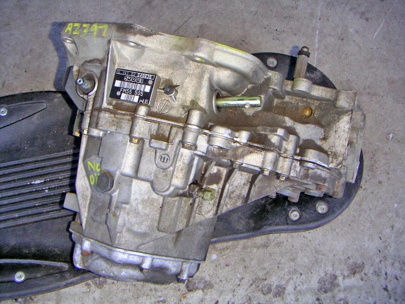
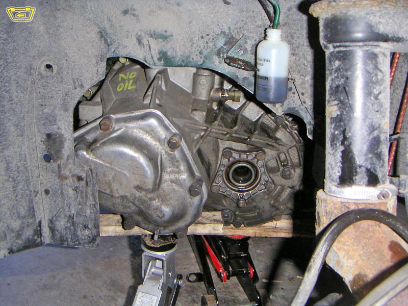
The replacement transmission came from a 1999 9-3. It's an FM55 505 model,
while the original gearbox on the car was FM55 501.
|
 |
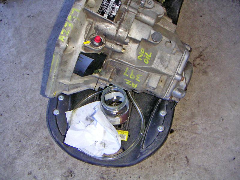
| 11.02.2006: Left side |
|
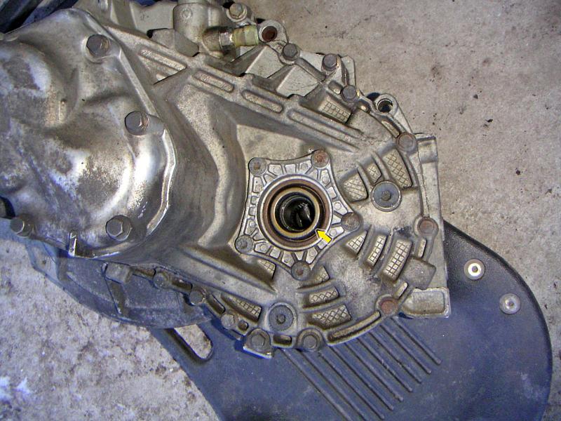
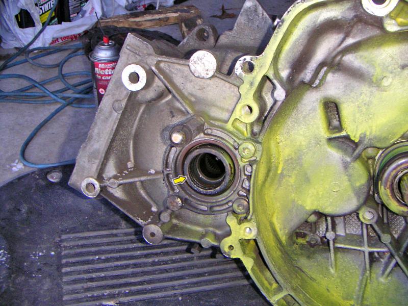
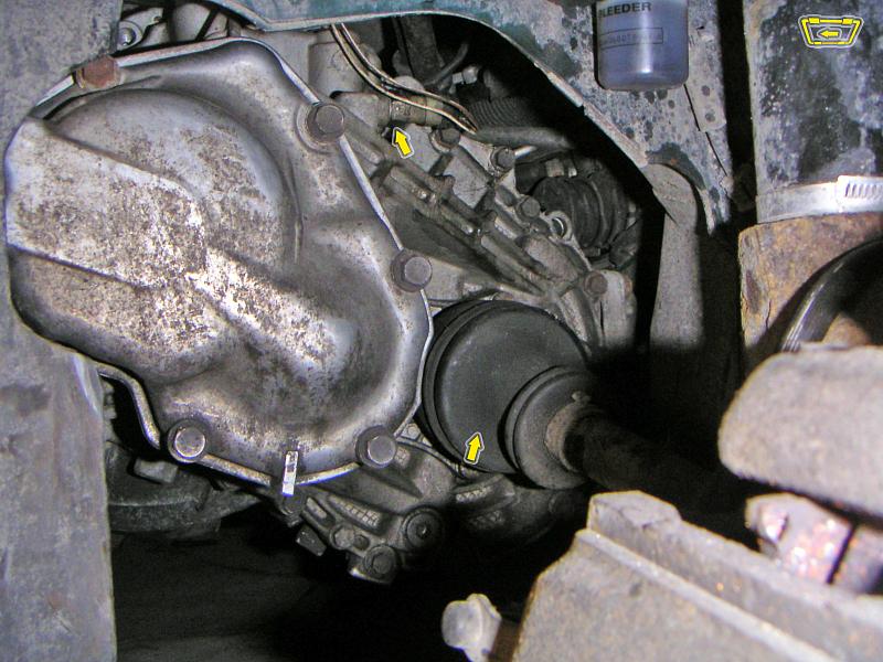
The new gearbox came from a scrap yard, so it's a good idea to replace
both differential seals.
|
 |
| 11.02.2006: Seals |
|
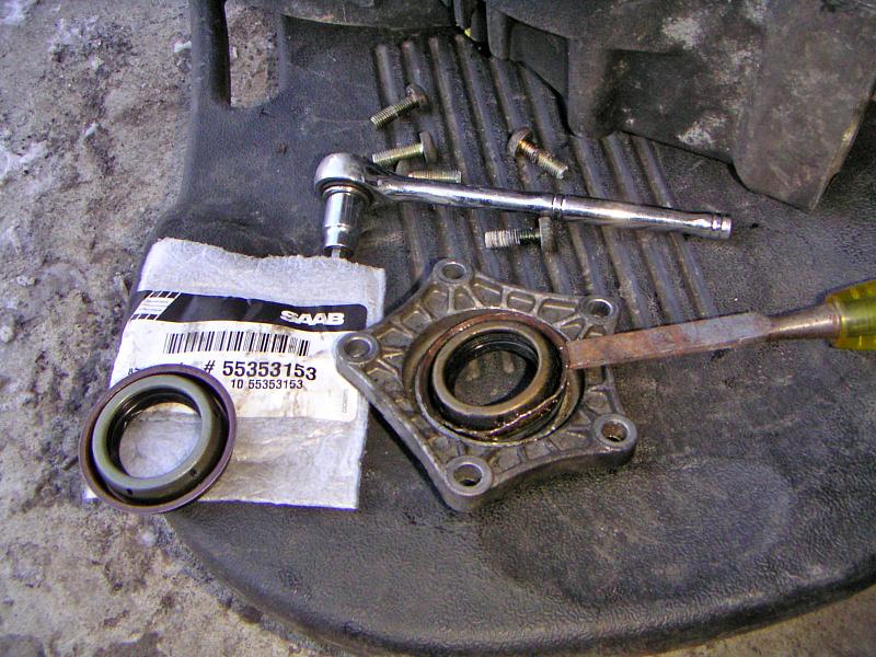
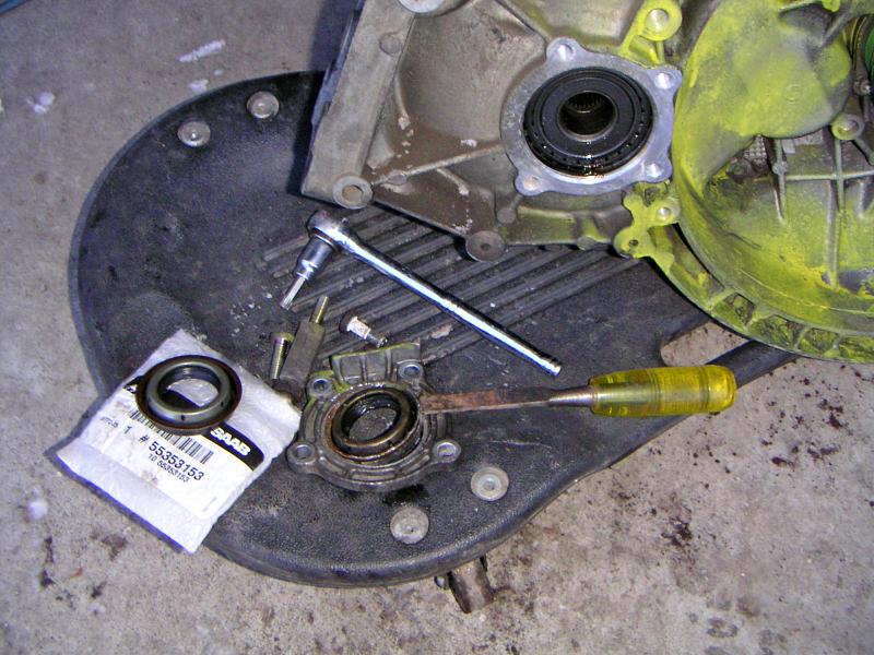
Pry the new seal out using a big screwdriver or a chisel. It's not
necessary to remove the entire cover, but I find it easier than doing
it right on the gearbox.
|
 |
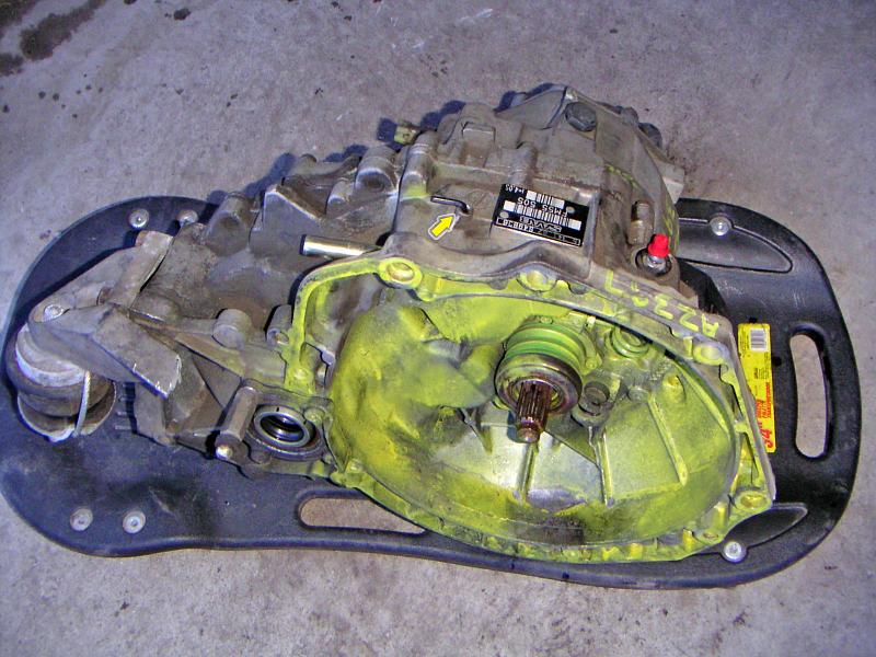
| 11.02.2006: Cover in |
|
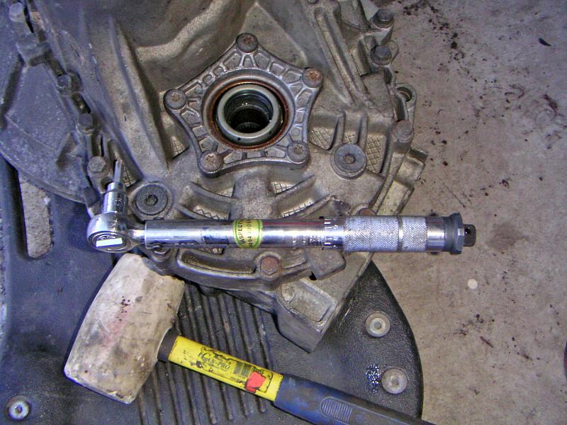
Carefully push the new seal in, use a rubber mallet if needed. Install
the cover back on and tighten the bolts to 16 ft-lbs with a Torx T40 socket.
|
 |
| 11.02.2006: Right side |
|
Do the same on the right side of the differential.
|
 |
| 11.02.2006: Seals |
|
The bag shows a GM part number (useful if your dealer uses those, like
they do in Canada). The Saab part is #8749046.
|
 |
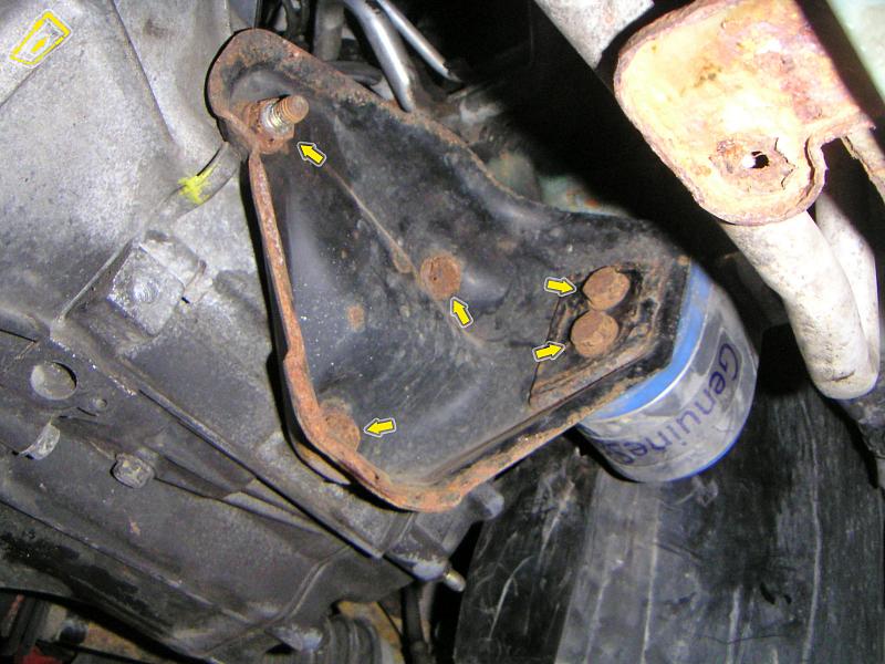
| 11.02.2006: Rear mount |
|
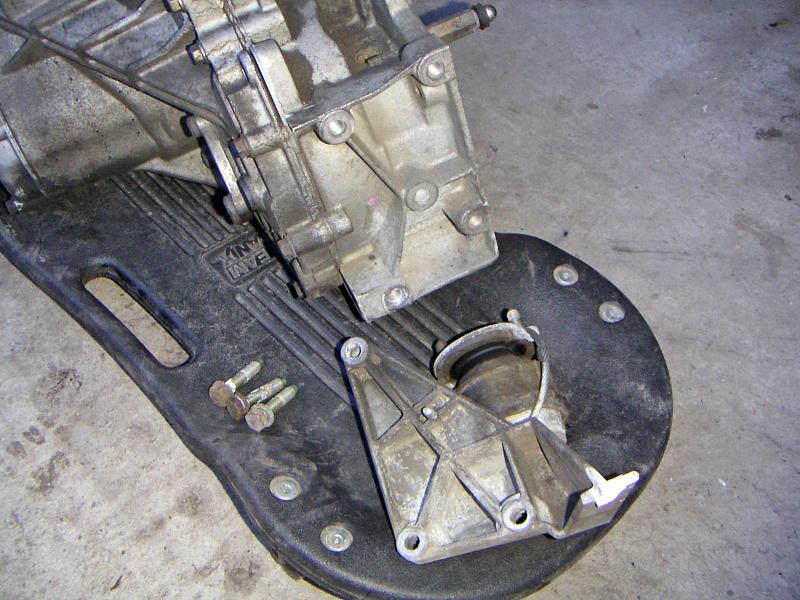
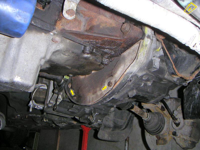
Attach the rear engine mount (30 ft-lbs, 16 mm socket). For a
later transmission model, the mount bracket might be different -- check the
compatibility if you're upgrading to a newer gearbox.
|
 |
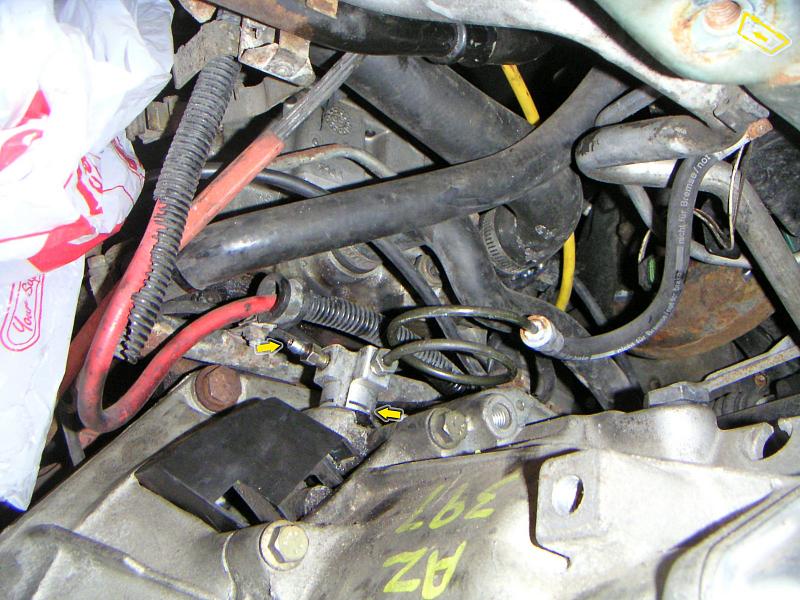
| 11.02.2006: Pipe |
|
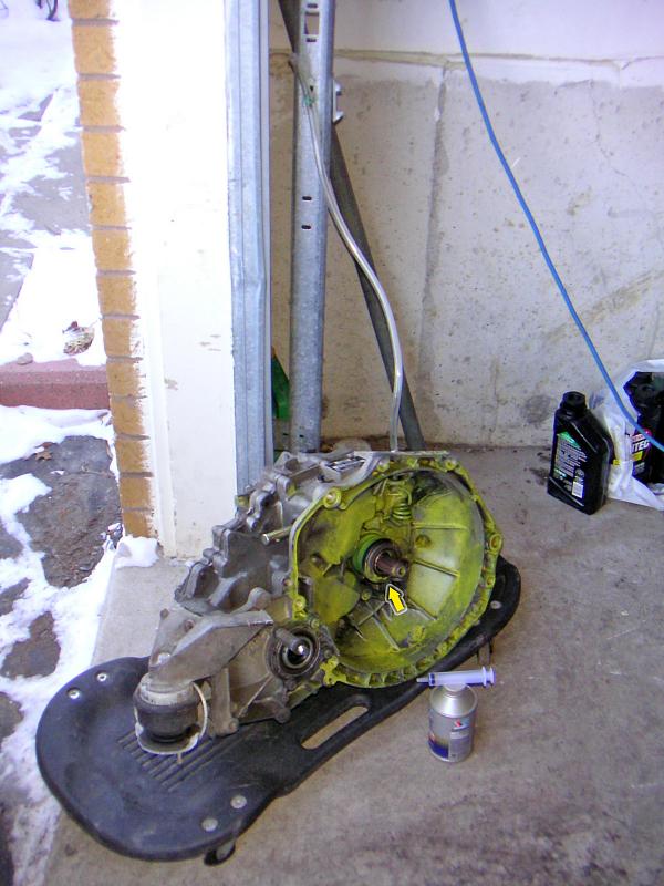
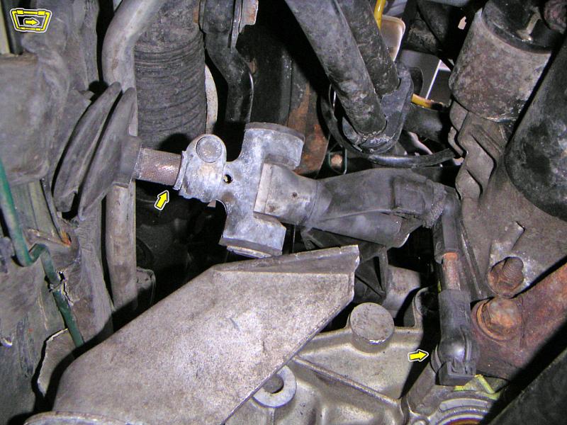
Time to bleed the slave cylinder. Push the throwout bearing in slowly to
compress the piston inside it. When you let go, the bearing will spring
back out, but the piston will remain compressed.
|
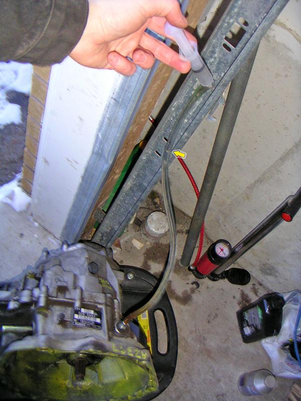 |
| 11.02.2006: Brake fluid |
|
Attach a 40..50 cm piece of clear tubing to nipple on top of the slave
cylinder. Fill the tube with brake fluid to ¾ of its height.
|
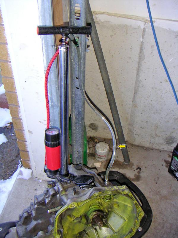 |
| 11.02.2006: Pressure |
|
Pump some air into the tube. The slave cylinder will expand, and you will
see the fluid level dropping. When the cylinder maxes out, the fluid will
stop and the pressure will go up. Release the pressure and compress
the slave again. You might see small air bubbles coming out.
|
 |
| 11.02.2006: Bleeding finished |
|
Repeat the process several times, add more brake fluid if necessary. When
you don't see the bubbles anymore, detach the hose (careful not to
spill the fluid all over) and plug the nipple.
|
 |
| 11.02.2006: Ready |
|
Lock the transmission in third gear. Make sure you can undo the fill and
drain plugs (but keep them in). Lubricate the shaft splines.
The gearbox is ready for installation.
|
 |
| 11.02.2006: New clutch |
|
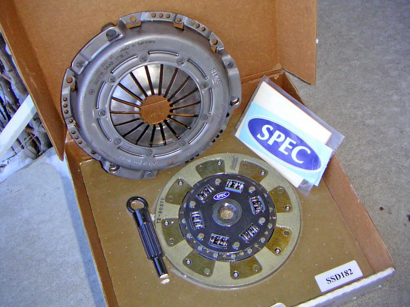
I am installing a Viggen pressure plate with a SPEC stage2 kevlar clutch
plate. The clutch conveniently comes with an alignment tool.
|
 |
| 11.02.2006: Flywheel |
|
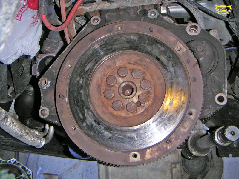
Inspect the flywheel. If it's visibly scratched or scored, or has cracks
on the surface, you need to take it to a machine shop for resurfacing.
Torque the bolts to 59 ft-lbs.
|
 |
| 11.02.2006: Alignment tool |
|
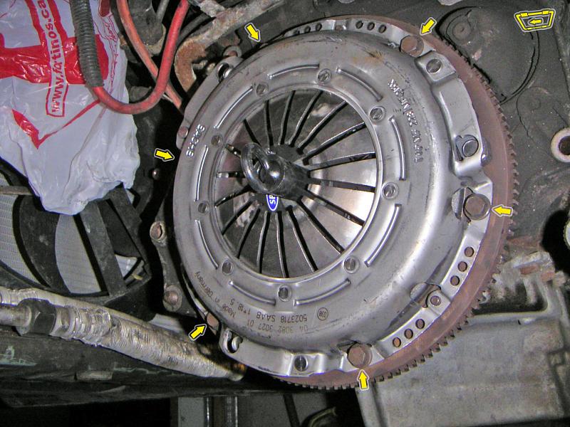
Install the clutch with the pressure plate and put the bolts in hand-tight.
Insert the alignment tool and make sure the clutch plate it perfectly
centered. Tighten the bolts alternately to 16 ft-lbs (12 mm socket).
|
 |
| 11.02.2006: Jacks |
|
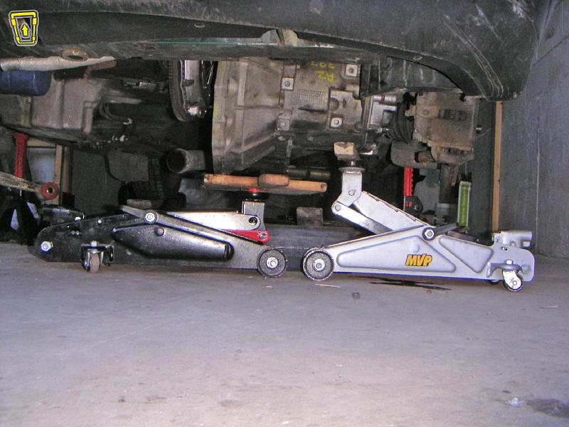
A specialized transmission jack or
a shop crane
is preferred, but a pair of
regular hydraulic jacks will do the job. Make sure the transmission is
balanced, roll it under the car and raise to the engine level.
|
 |
| 11.02.2006: Left side |
|
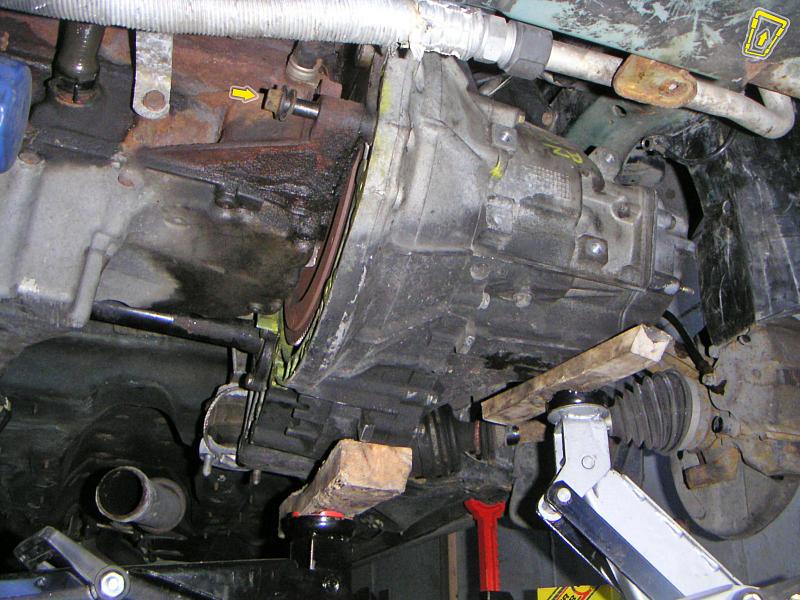
Push the transmission in. Remember that you have to match the splines on
the clutch plate and the intermediate shaft in the same time. If necessary,
turn the flywheel and/or the driveshaft on the right side. The picture
shows the brake line disconnected, it was a part of
another job.
|
 |
| 11.02.2006: Fitted |
|
The transmission should be perfectly level with the engine in order to go
in. Again, a lower control arm bolt works well as a guiding pin. Once you
close the gap and the intermediate shaft snaps in on the other side,
replace the front bolt with a proper one and tighten it.
|
 |
| 11.02.2006: Upper bolts |
|
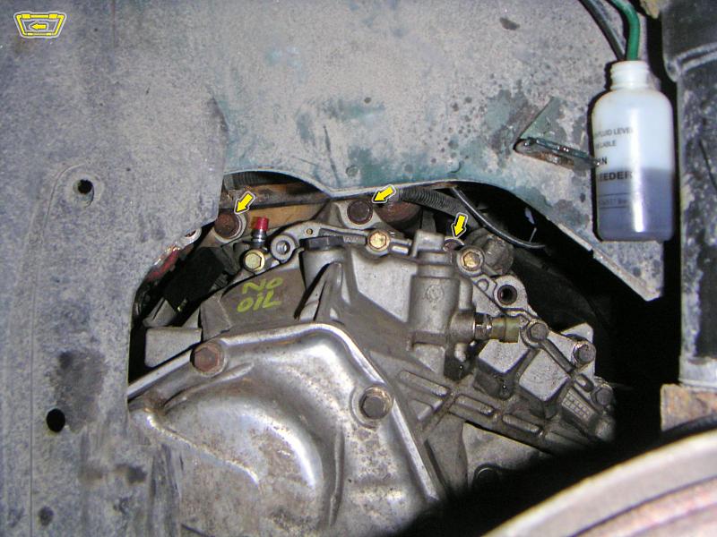
The three upper bolts are easily accessible from the wheel well, just use a
longer extention. Don't forget the fifth bolt in the rear. The torque for
these is 50 ft-lbs (18 mm socket).
|
 |
| 11.02.2006: Clutch line |
|
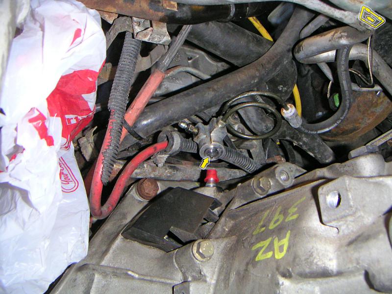
Remove the cap from the slave cylinder nipple and attach the clutch line.
If you have a cable clutch, attach the cable.
|
 |
| 11.02.2006: Clutch line |
|
Insert a locking clip to secure the clutch line. The nipple in front will
be used to bleed the clutch once the job is done.
|
 |
| 11.02.2006: Bracket |
|
Attach the bracket for the transmission mount, as well as the mount
itself (30 ft-lbs, 16 mm socket).
|
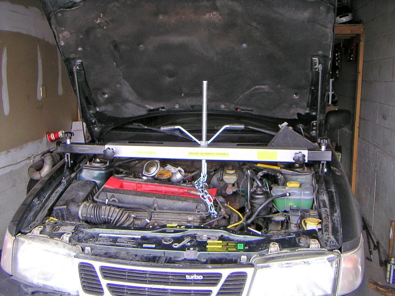 |
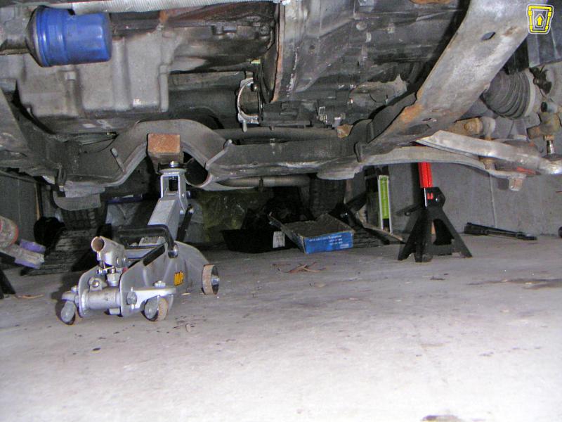
| 11.02.2006: Support beam |
|
Raise the engine until the transmission mount fits its position on the
side member.
|
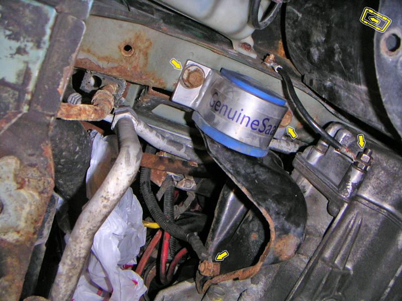 |
| 11.02.2006: Mount |
|
Tighten the transmission mount bolts to 46 ft-lbs (15 mm socket). Attach
the ground wires to the mount bracket, and to the side of the gearbox
(17 mm and 13 mm sockets).
|
 |
| 11.02.2006: Driveshaft |
|
Insert the driveshaft until the snap ring clicks. Plug in the reverse gear
sensor wire.
|
 |
| 11.02.2006: Flywheel cover |
|
Install the flywheel cover (two 11 mm bolts).
|
 |
| 11.02.2006: Linkage |
|
Attach the linkage to the gearshift rod on the transmission (13 mm bolt),
connect the arm to the ball pin and insert the shifter rod into its housing.
After the entire installation is finished, the shifter needs to be
aligned.
|
 |
| 11.02.2006: Subframe |
|
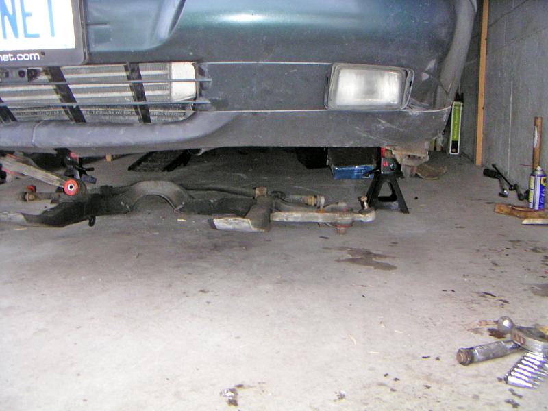
Position the subframe for installation.
|
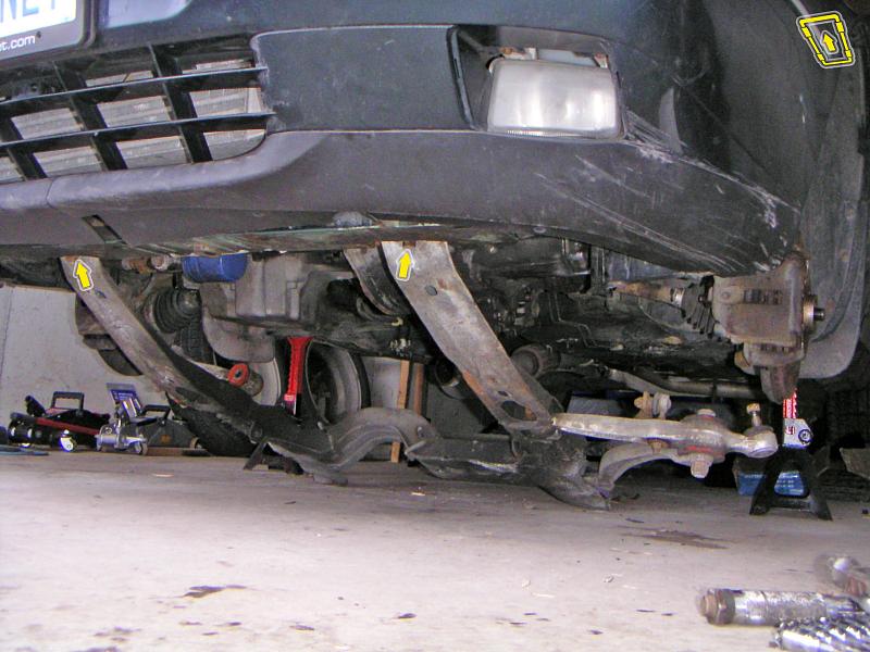 |
| 11.02.2006: Front bolts |
|
First, raise the front end and screw the bolts in hand-tight.
|
 |
| 11.02.2006: Washers |
|
Place the washers on the stanchion arm attachment points.
|
 |
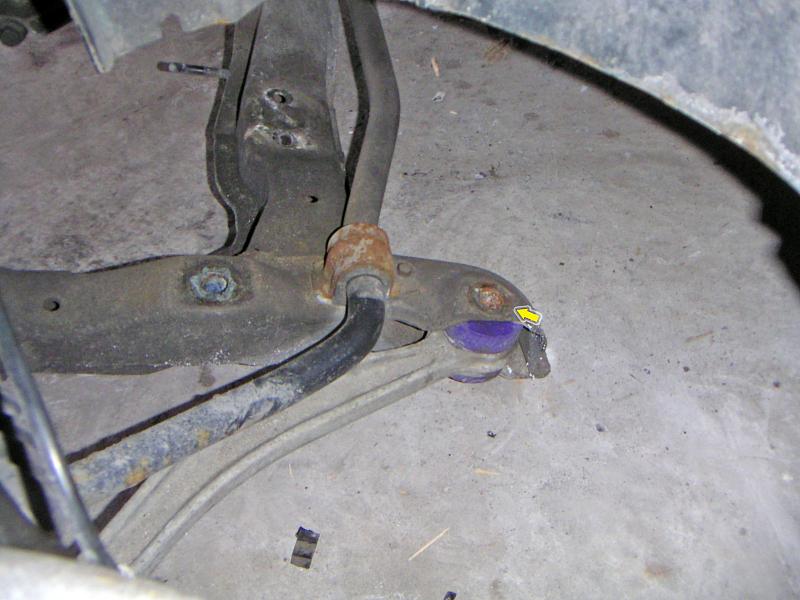
| 11.02.2006: Rear end |
|
Jack up the rear end, insert the remaining bolts and align the subframe
so it matches the position it was in before the removal. Connect the
ball joints and tighten to 55 ft-lbs (18 mm wrench).
|
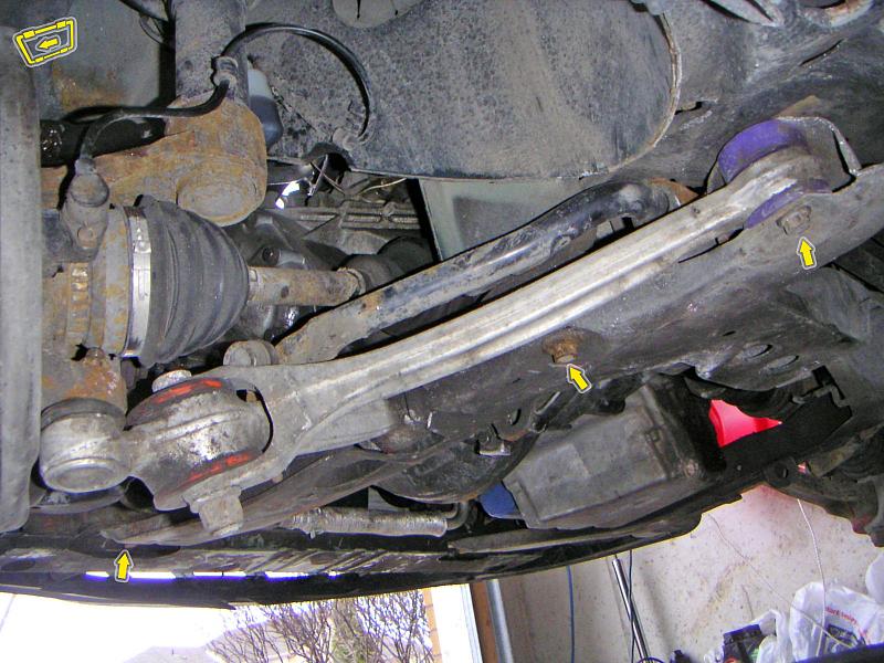 |
| 11.02.2006: Subframe bolts |
|
Tighten the four corner bolts using a 16 mm socket: front to 85 ft-lbs
and rear to 78 ft-lbs + 90°. Tighten the middle bolts to
141 ft-lbs (18 mm socket). If you had to remove the control arms, they
need a 15 mm socket at 85 ft-lbs.
|
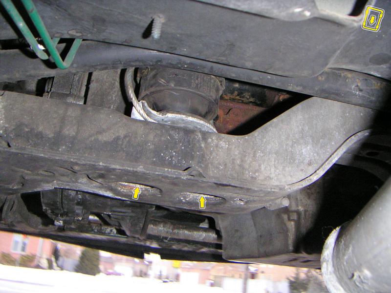 |
| 11.02.2006: Rear mount |
|
Tighten the nuts on the rear engine mount to 37 ft-lbs (16/17 mm socket).
|
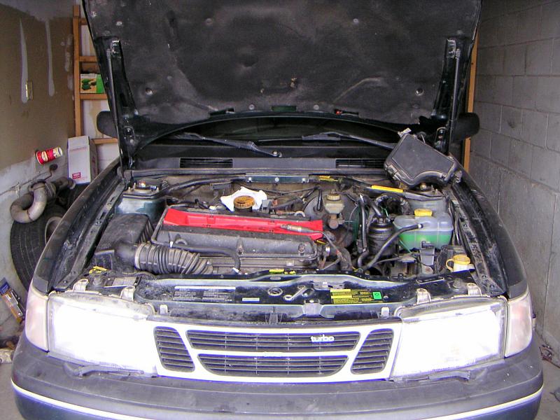 |
| 11.02.2006: Beam removed |
|
Remove the engine support beam.
|
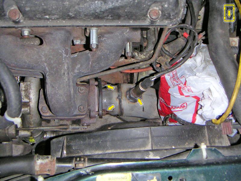 |
| 11.02.2006: Downpipe |
|
Attach the downpipe to the turbo (three 13 mm nuts at 18.5 ft-lbs).
Install the front O2 sensor (22 mm crowfoot wrench, 41 ft-lbs).
|
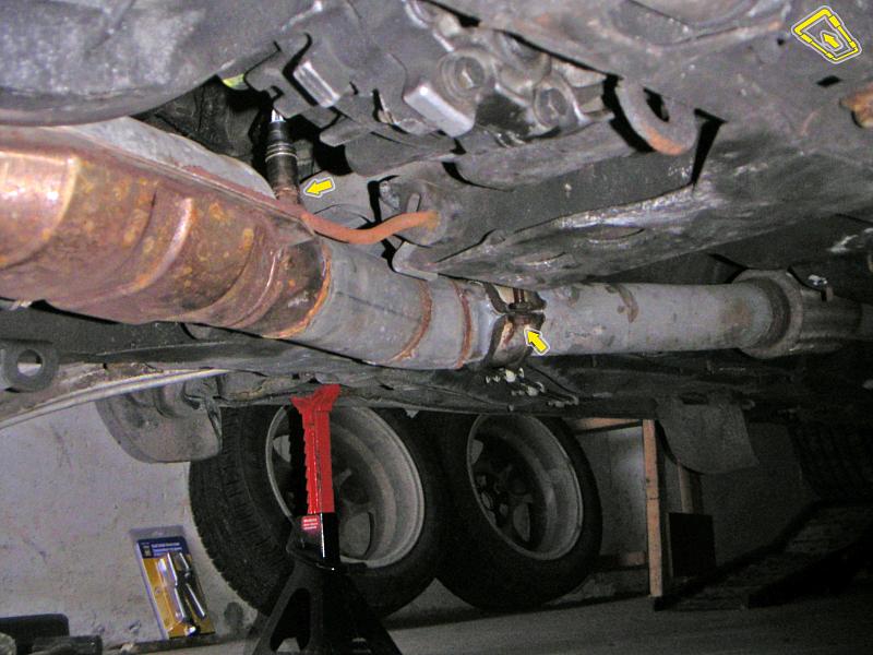 |
| 11.02.2006: Exhaust |
|
Install the rear O2 sensor (22 mm crowfoot wrench, 41 ft-lbs). Seal the
joint to the flexpipe and tighten the clamp to 15 ft-lbs (13 mm socket).
Install the subframe brace if equipped.
|
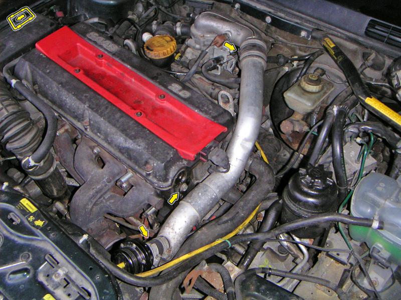 |
| 11.02.2006: Delivery pipe |
|
Install the delivery pipe and tighten the hose clamps. Attach the hoses
to the bypass valve. Bleed the clutch, shift the transmission to fourth
gear and
align
the shifter linkage.
|
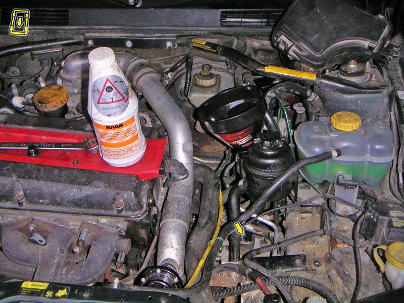 |
| 11.02.2006: Gearbox oil |
|
Fill the gearbox with oil (flush twice if switching to synthetic).
Install the battery. Attach the lower shields. Fit the wheels (81 ft-lbs)
and lower the car to the ground.
|


