 |
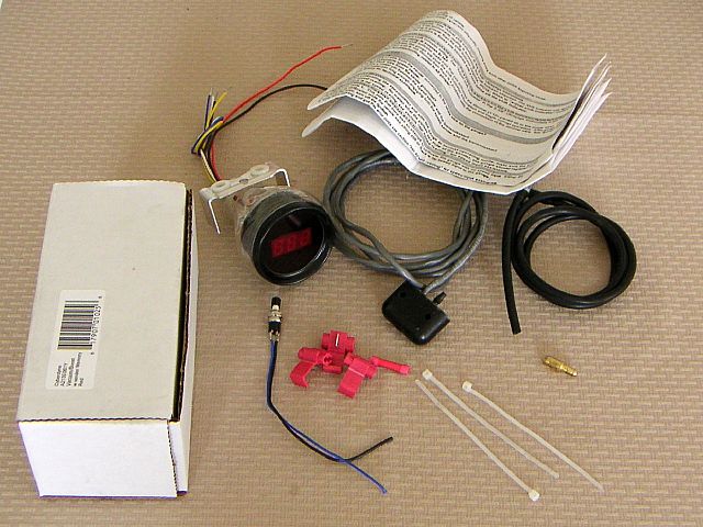
| 17.04.2004: The kit |
|
A Cyberdyne Ultragage boost/vacuum gauge kit (part #A213E061Y) bought
on eBay. It contains a gauge, a sender, some tubing and other stuff.
|
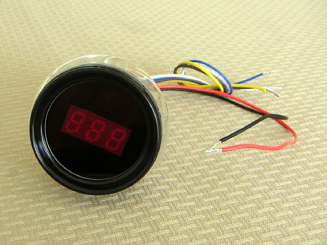 |
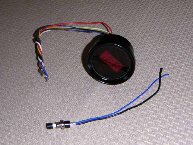
| 17.04.2004: The gauge |
|
I know I could've gotten an analog gauge for half the price, but I'm a
digital freak, I like numbers and precision ;).
|
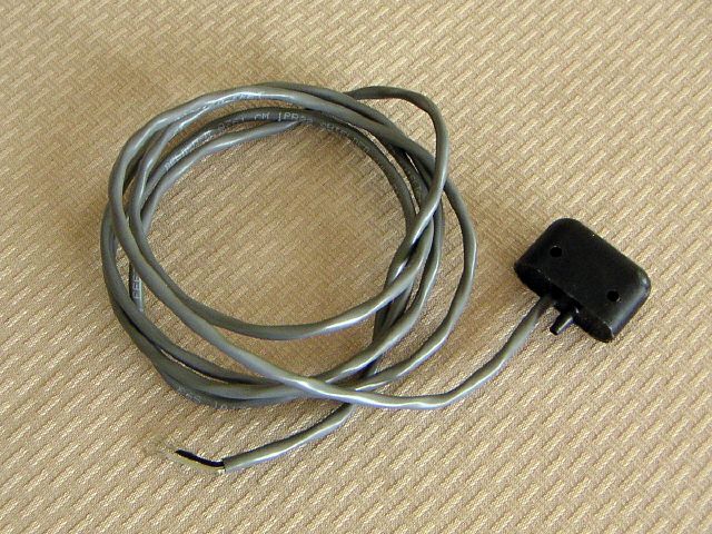 |
| 17.04.2004: The sending unit |
|
The sending unit is sealed for good, it has a nipple for the vacuum hose and
a signal wire for the gauge.
|
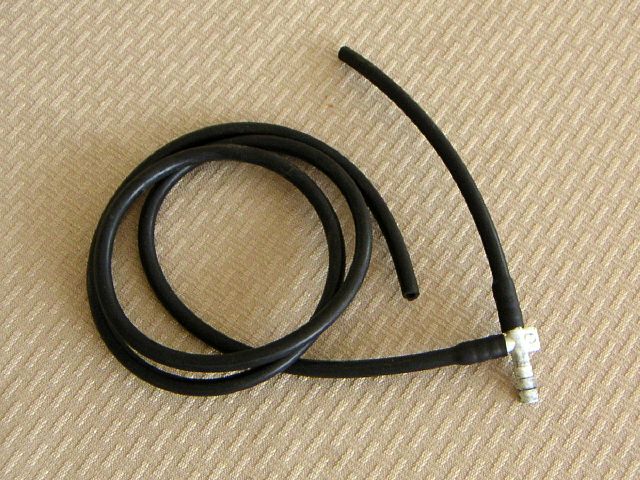 |
| 17.04.2004: The hose |
|
The tees are a buck a piece from your favourite parts store. This one is
dirty as I've just tried to fit it on a car.
|
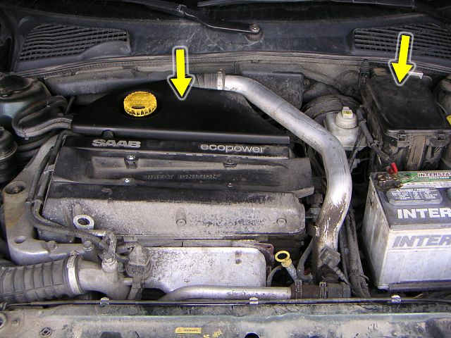 |
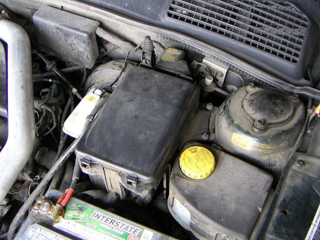
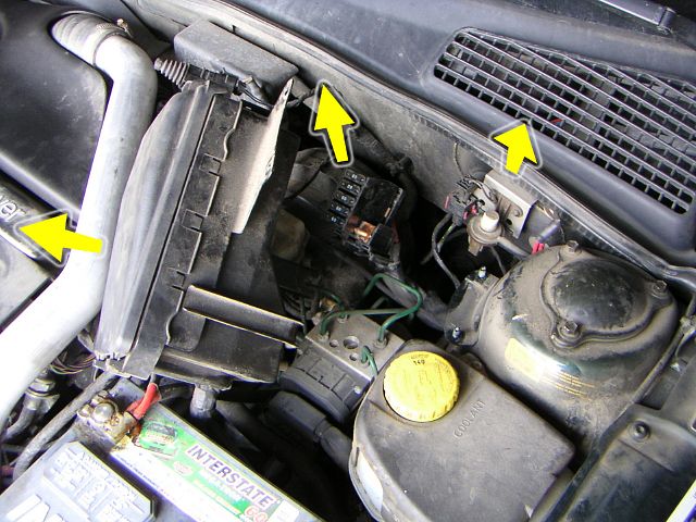
| 17.04.2004: The engine |
|
Our primary points of interest today would be the intake manifold and the
big fuse box. The engine is filthy, and I'm sorry for that. Should have
done the spring cleaning first.
|
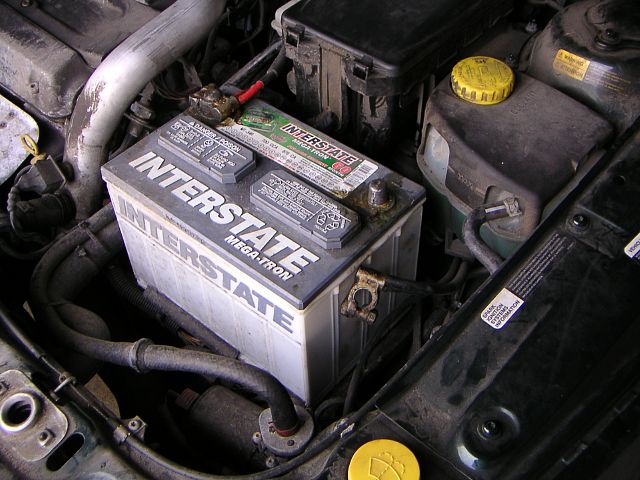 |
| 17.04.2004: Disconnecting the battery |
|
Always a good idea when you're planning to mess with wiring.
|
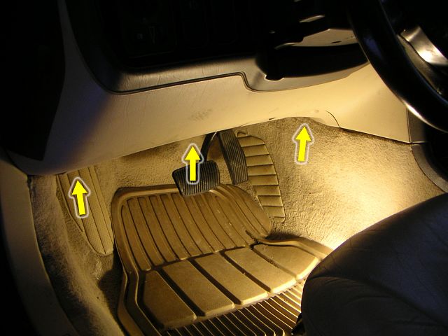 |
| 17.04.2004: The lower dash |
|
To find a suitable place to get through the firewall, remove the lower
dash cover. There are three T25 torx screws holding it.
|
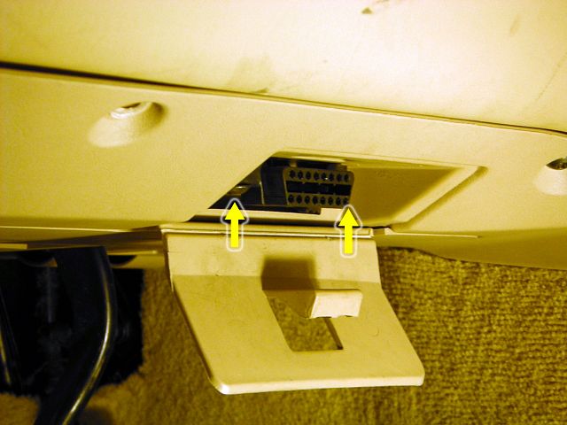 |
| 17.04.2004: OBD-II connector |
|
Remove two more screws, unless you want the cover hanging on the OBD-II
connector wires.
|
 |
| 17.04.2004: Holes in the firewall |
|
A sysadmin would be shocked by a sentence like this ;). In our case in only
means there are two clusters of wires coming through the firewall.
|
 |
| 17.04.2004: Fuse boxes |
|
Looking from the engine side, the access to one cluster is blocked by the
strut tower and the fuse boxes are blocking the other. I pick the fuse boxes.
|
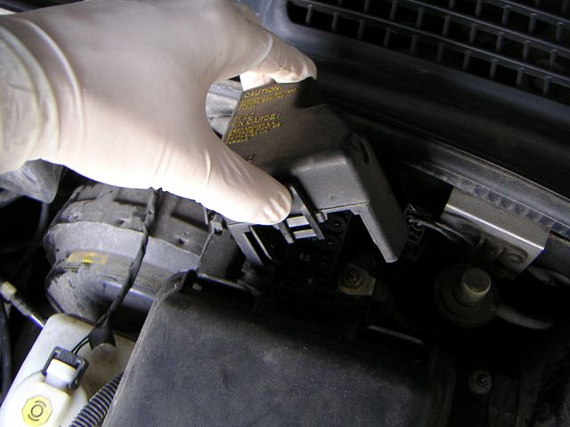 |
| 17.04.2004: Small fuse box |
|
First, remove the cover from the smaller box.
|
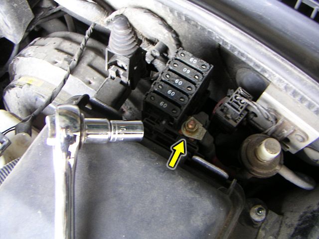 |
| 17.04.2004: Disconnecting the cables |
|
Then unbolt the cables using a 10 mm socket.
|
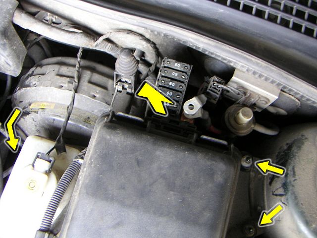 |
| 17.04.2004: Removing components |
|
Push the latches, and the smaller box pops right up. The bigger box is
secured with three nuts -- two are in the open, and the third one is under
the master brake cylinder.
|
 |
| 17.04.2004: Almost there |
|
Move the fuse boxes out of the way and remove another connector assembly
(lift the rubber trim to get it out).
|
 |
| 17.04.2004: The cable sleeve |
|
The rubber sleeve around the cables is ziptied and wrapped with dirty
vinyl tape. We'll get rid of that.
|
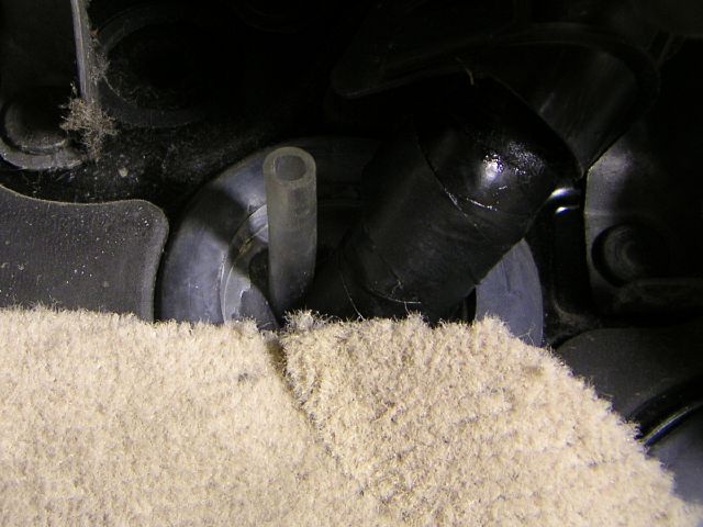 |
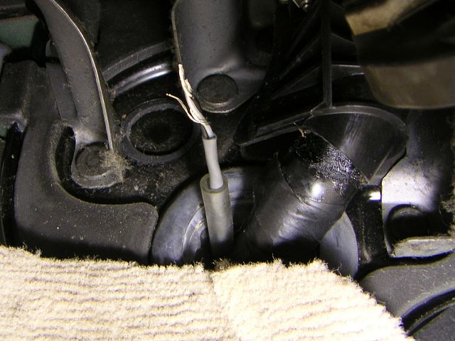
| 17.04.2004: A handy pipe |
|
The sender cable is rather soft, so I will use this plastic pipe to get
the wire through the sleeve.
|
 |
| 17.04.2004: The engine side |
|
After some pushing and wiggling the pipe comes out on the engine side.
|
 |
| 17.04.2004: Inserting the wire |
|
The wire goes in...
|
 |
| 17.04.2004: Coming through |
|
...and comes out under the dash.
|
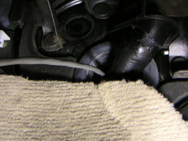 |
| 17.04.2004: Pipe removed |
|
Find a good way to pass the cable to the top of the dash to the A-pillar
and fasten it.
|
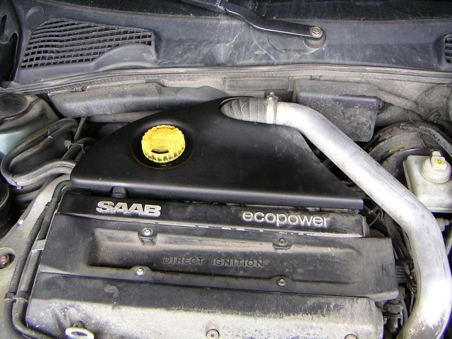 |
| 17.04.2004: Engine cover |
|
Now we need to find a place to tap for the boost pressure. First, remove
the engine cover.
|
 |
| 17.04.2004: Cover removed |
|
A nipple on top of the intake manifold looks very promising.
|
 |
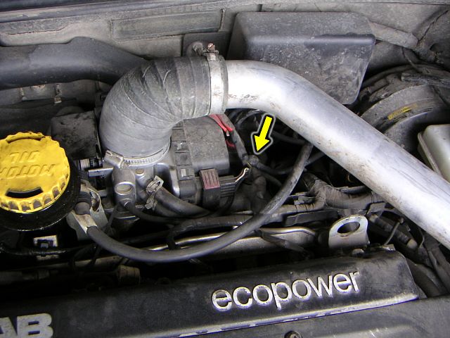
| 17.04.2004: Front view |
|
There are two hoses coming out of it, and the top one is so inviting!
|
 |
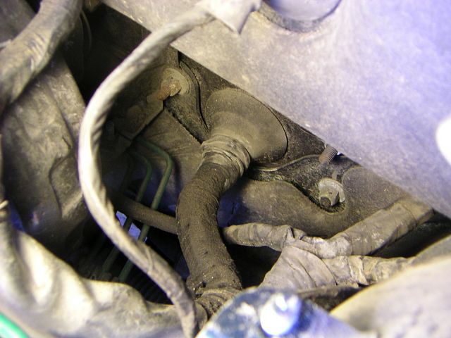
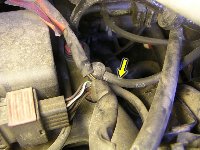
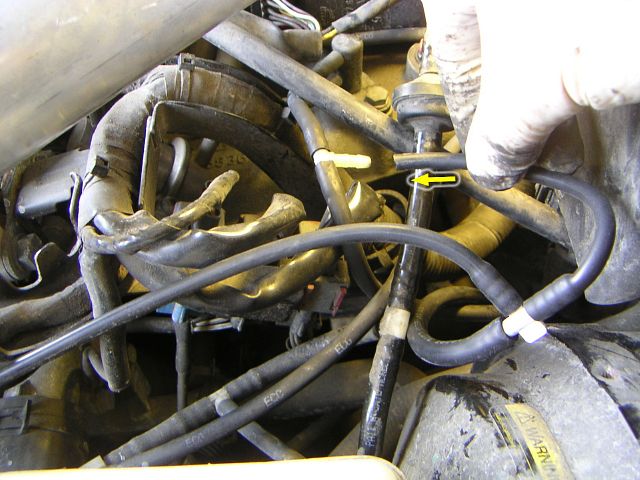
| 17.04.2004: Side view |
|
It usually is not a good idea to cut the hoses on a car, and fortunately
there's a conveniently placed tee we could tap into.
|
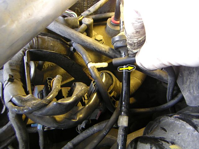 |
| 17.04.2004: Removing the hose |
|
First, remove one of the old hoses from the tee.
|
 |
| 17.04.2004: Old hose to new tee |
|
Then connect it to the new tee we prepared during the step 4.
|
 |
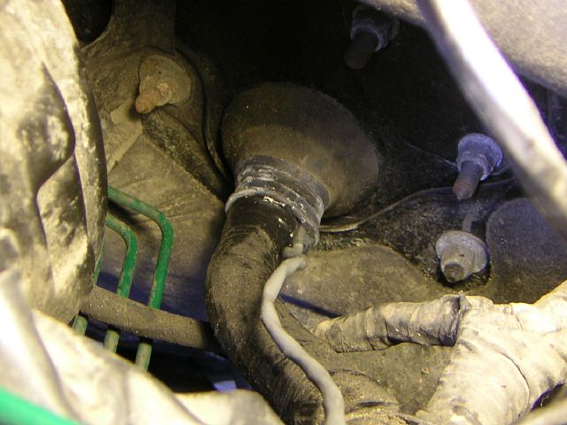
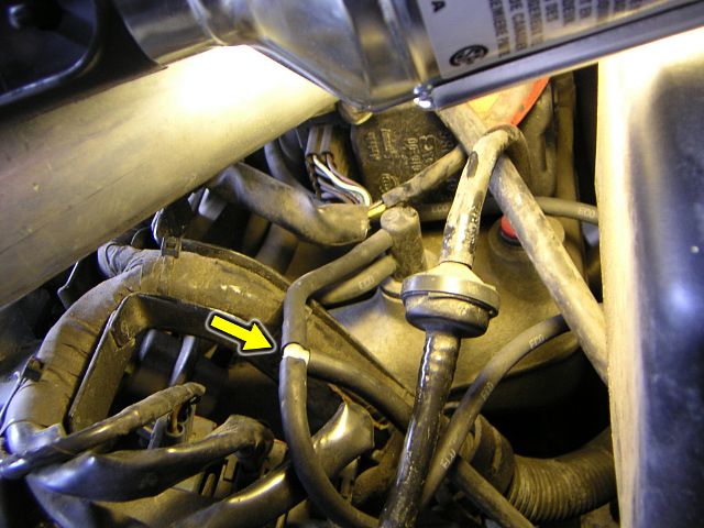
| 17.04.2004: New hose to old tee |
|
And finally connect the short end of the hose to the original tee.
|
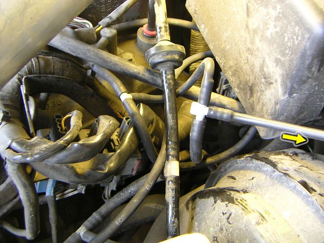 |
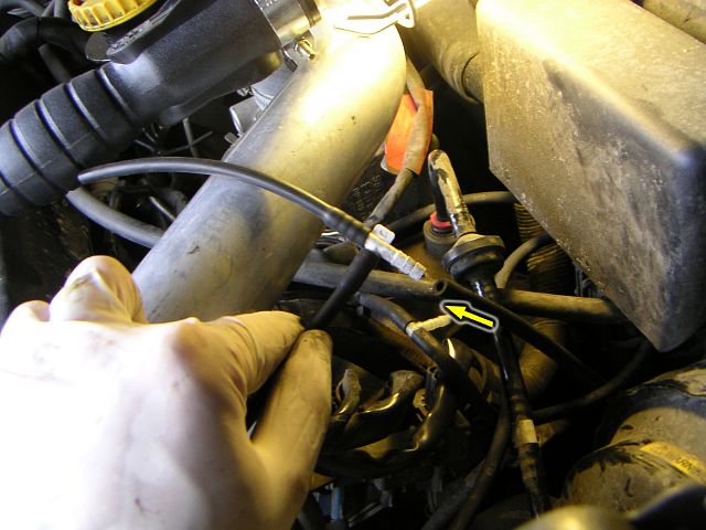
| 17.04.2004: Lots of hoses |
|
This piece would be easy to remove later in case you'd want to sell the car.
The long end in the right now runs to the sending unit.
|
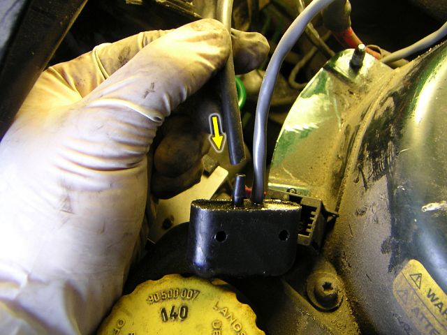 |
| 17.04.2004: The sending unit |
|
Time to connect it to the unit and secure the new hose so it doesn't rub
against anything.
|
 |
| 17.04.2004: Pulling the wire in |
|
Pull the remaining cable through the sleeve leaving only a short end.
Seal the sleeve with a new ziptie and some tape.
|
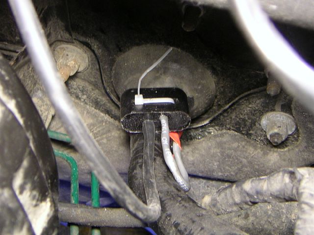 |
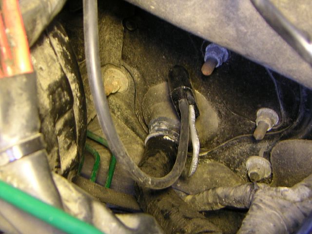
| 17.04.2004: Securing the unit |
|
Fasten the sending unit well and bolt the fuse boxes back in place.
Check if everything is connected properly.
|
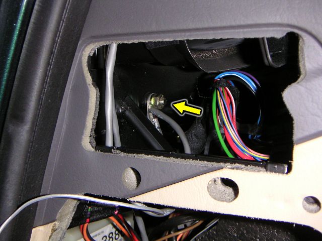 |
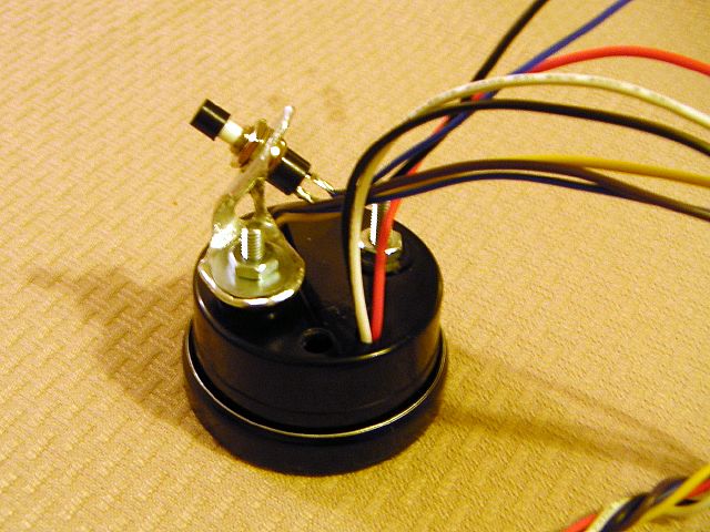
| 17.04.2004: Connecting the wires |
|
The gauge needs the ground and the 12V power. The ground nut is right at
hand (10 mm again) and the cigarette lighter fuse would donor the power.
|
 |
| 17.04.2004: Test drive |
|
Out for a test drive. A healthy 20 Hg vacuum at idle is on display.
|
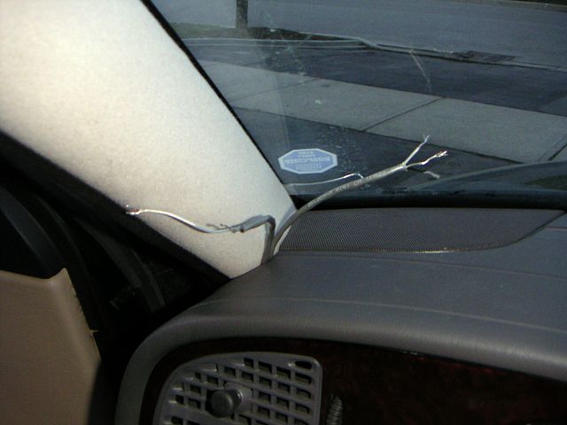 |
| 17.04.2004: Wiring done |
|
Everything is put back together, and the wires are coming out at the
base of the A-pillar.
|
 |
| 17.04.2004: The gauge |
|
The gauge comes with a memory button. Why haven't they just built it right
into the face plate?
|
 |
| 17.04.2004: Button installed |
|
Ah, well, an aluminum bracket will do.
|
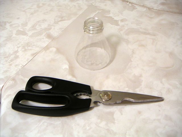 |
| 17.04.2004: Plastic bottle |
|
I didn't get a pod for the gauge, and now I didn't want it dangling on its
wires while I'm driving in search for one, so I cut the top of a plastic
bottle.
|
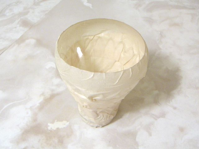 |
| 17.04.2004: Masking tape |
|
Painting it inside looked like a good idea.
|
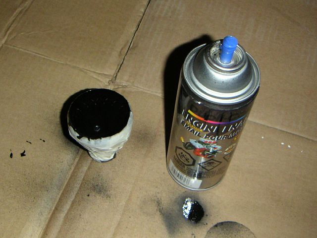 |
| 17.04.2004: All black |
|
Luckily, I had some black paint too.
|
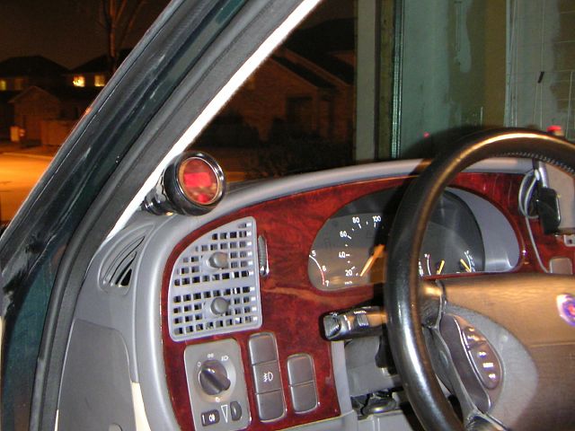 |
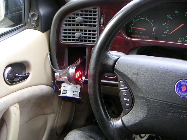
| 17.04.2004: Mounted |
|
The wires are connected, and the gauge sticks surprisingly tight between
the pillar and the dash. It should hold until I find a suitable pod.
|
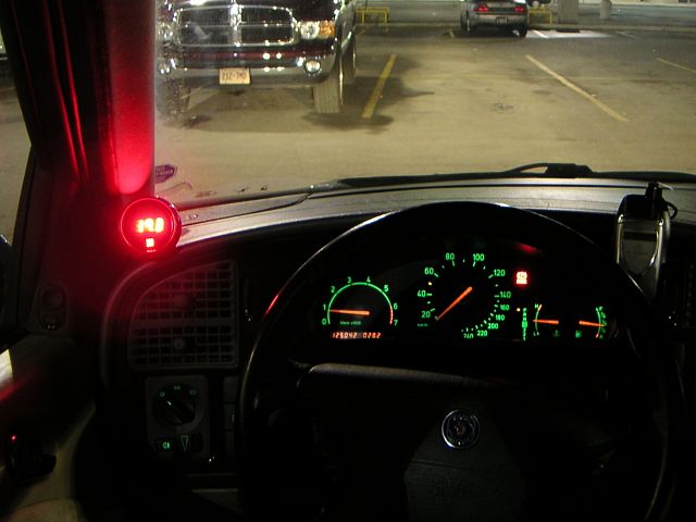 |
| 17.04.2004: Night |
|
It's a bit too bright at night, but we'll adjust that.
|
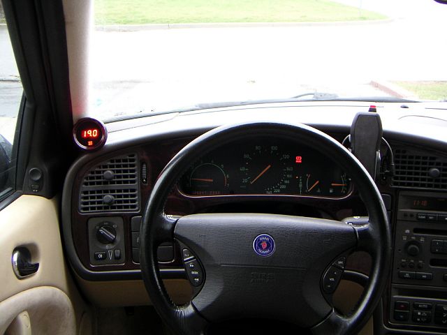 |
| 18.04.2004: Day |
|
Good visibility in the daylight.
|


